IPC · Section B & C · Free response

Mechanics and Energy

28 questions — reveal each answer and worked solution.

2010-13C · Writtend4Mechanics and Energy · Terminal velocity and drag force

(2010-13: Free fall and air resistance) A package is dropped from rest from a very tall tower and then, after some time, a parachute opens to slow the package down.
Initially the parachute is closed and the whole package is approximately a sphere of radius 50 cm and mass 40 kg .
As the package falls through the air, the drag force increases as the velocity increases and, eventually, the package achieves its terminal velocity.

The drag force (D) acting on the package is given by the equation:
Drag force $=$ constant $(\mathrm{k}) \mathrm{x}$ cross sectional area $(\mathrm{A}) \mathrm{x}$ velocity $(\mathrm{v})$ squared $\mathrm{D}=\mathrm{kAv}{ }^{2}$
where: $\mathrm{k}=0.7 \mathrm{Ns}^{2} / \mathrm{m}^{4}$
A is the cross sectional area of the sphere
(i.e. the area of a circle of the same radius)
v is the velocity
(a) Show that the terminal velocity of the package before the parachute opens is approximately $27 \mathrm{~m} / \mathrm{s}$.
(b) Without further calculation, state and explain how the terminal velocity would be affected if the 40 kg package had a higher density than the package considered in (a).
The package considered in part (a) is travelling at its terminal velocity when the parachute is opened.

Assume the stated drag formula also applies to the parachute when it is open.
(c) Estimate the area of the parachute needed to reduce the terminal velocity of the package to $10 \mathrm{~m} / \mathrm{s}$.
(d) Calculate the resultant force acting on the package and parachute immediately after the parachute opens (assume the parachute opens instantly so that the parachute is initially moving at $27 \mathrm{~m} / \mathrm{s}$ ).
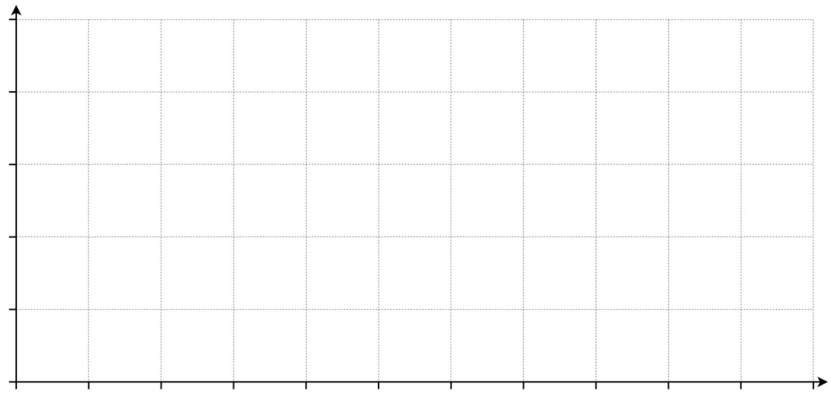
(e) In the space below draw an acceleration-time graph for the package from the moment it is released from rest until after the parachute opens and it achieves a final terminal velocity of $10 \mathrm{~m} / \mathrm{s}$.
Include a scale on the acceleration axis to show all significant values.
It is not necessary to indicate a scale on the time axis.

Show worked solution
(a)

At terminal velocity the acceleration is zero, so the resultant force is zero and the weight is balanced by the drag force: $$ mg=D=kAv_t^2 $$ The package is a sphere of radius $r=0.50\,\mathrm{m}$, so its cross-sectional area is the area of a circle: $A=\pi r^2=\pi(0.50)^2=0.25\pi\approx 0.785\,\mathrm{m}^2$. Using $m=40\,\mathrm{kg}$, $g=9.8\,\mathrm{m\,s^{-2}}$, and $k=0.7\,\mathrm{Ns^2\,m^{-4}}$: $$ v_t=\sqrt{\frac{mg}{kA}}=\sqrt{\frac{40\times 9.8}{0.7\times 0.785}} =\sqrt{\frac{392}{0.5495}} =\sqrt{713.6}\approx 26.7\,\mathrm{m\,s^{-1}}\approx 27\,\mathrm{m\,s^{-1}} $$ So the terminal velocity before the parachute opens is approximately $27\,\mathrm{m\,s^{-1}}$.

(b)

If the package has the same mass ($40\,\mathrm{kg}$) but higher density, it must have a smaller volume and therefore a smaller radius, giving a smaller cross-sectional area $A$. Since terminal speed satisfies $v_t=\sqrt{mg/(kA)}$, decreasing $A$ makes $mg/(kA)$ larger, so $v_t$ increases. The package would fall faster because it presents a smaller area to the airflow for the same weight.

(c)

For the new terminal velocity $v_t=10\,\mathrm{m\,s^{-1}}$ with the parachute open, the terminal condition is again $mg=kAv_t^2$, now with $A$ being the effective cross-sectional area of the parachute (dominant compared with the package): $$ A=\frac{mg}{kv_t^2}=\frac{40\times 9.8}{0.7\times 10^2} =\frac{392}{70}=5.6\,\mathrm{m}^2 $$ So the parachute area needed is approximately $5.6\,\mathrm{m}^2$.

(d)

Immediately after opening, the speed is still $v=27\,\mathrm{m\,s^{-1}}$ but the area is now $A=5.6\,\mathrm{m}^2$, so the drag is $$ D=kAv^2=0.7\times 5.6\times 27^2 =(3.92)\times 729\approx 2.86\times 10^3\,\mathrm{N} $$ Drag acts upward while weight $mg=392\,\mathrm{N}$ acts downward, so the resultant force is upward with magnitude $$ F_{\text{res}}=D-mg\approx 2.86\times 10^3-392\approx 2.47\times 10^3\,\mathrm{N} $$ The acceleration magnitude is $a=F_{\text{res}}/m\approx (2.47\times 10^3)/40\approx 61.6\,\mathrm{m\,s^{-2}}$, directed upward (so it is a deceleration of the downward motion).

(e)

Take downward acceleration as positive. From release, $v=0$ so $D=0$ and $a=+g\approx +9.8\,\mathrm{m\,s^{-2}}$; as speed increases, $D=kAv^2$ increases, so the net downward force decreases and $a$ smoothly falls toward $0$ as the first terminal speed $27\,\mathrm{m\,s^{-1}}$ is approached. When the parachute opens, the drag suddenly increases at the same instant speed ($27\,\mathrm{m\,s^{-1}}$), giving a sudden jump in acceleration to a large upward value $a\approx -61.6\,\mathrm{m\,s^{-2}}$, and then as the package slows toward the new terminal speed $10\,\mathrm{m\,s^{-1}}$, the drag decreases until it again balances weight, so $a$ rises back up to $0$ from below. A suitable sketch (with significant acceleration values marked) is:

$$ \begin{tikzpicture}[x=1.0cm,y=0.06cm] \draw[->] (0,0) -- (12,0) node[right] {time}; \draw[->] (0,-80) -- (0,20) node[above] {acceleration (m s$^{-2}$)}; \draw (-0.15,9.8) -- (0.15,9.8) node[left] {$+9.8$}; \draw (-0.15,0) -- (0.15,0) node[left] {$0$}; \draw (-0.15,-61.6) -- (0.15,-61.6) node[left] {$-62$}; \draw[thick,smooth] (0,9.8) .. controls (2,5) and (3.5,1.5) .. (5,0); \draw[dashed] (6,-80) -- (6,20) node[above] {parachute opens}; \draw[thick] (5,0) -- (6,-61.6); \draw[thick,smooth] (6,-61.6) .. controls (7,-35) and (8,-10) .. (10,0); \end{tikzpicture} $$
2010-14C · Writtend3Mechanics and Energy · Doppler effect — moving source

(2010-14: Sound from a moving car) A group of students investigates how the sound from a moving car appears to change its frequency (pitch) compared to when the car is stationary.

They use a model where water drops from a source moving at a constant speed cause ripples to spread out on the surface of a tank of still water.

In the model the ripples that spread out represent the sound waves from the moving car.
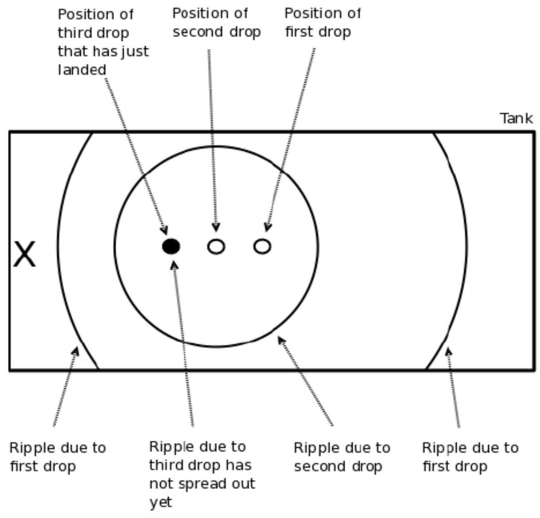
The diagram shows the position where three drops landed and the position of the ripples due to the first two drops. The third drop has only just landed and so the ripple has not spread out yet.

figure

The ripples travel at speed $\mathrm{v}=9.0 \mathrm{~cm} / \mathrm{s}$
The source moves at speed $c=4.0 \mathrm{~cm} / \mathrm{s}$
The drops occur every half second
(a) State the frequency at which the drops are released
(b) Show that the time interval between successive ripples arriving at point X is 0.28 s
(c) State the frequency of the waves arriving at point X
When a car is stationary the horn has a frequency of 300 Hz .
When the car moves at $5.00 \mathrm{~m} / \mathrm{s}$ towards an observer the horn appears to have a slightly higher frequency.
(d) By calculating the time period of the sound and referring to the model described previously, estimate the frequency of the horn that the observer hears.
(speed of sound $=340 \mathrm{~m} / \mathrm{s}$ )

Show worked solution
(a)

The frequency $f$ at which the drops are released is the reciprocal of the time interval between drops. Since the drops occur every 0.5 seconds, the frequency is given by:

$$ f = \frac{1}{T} = \frac{1}{0.5 \, \mathrm{s} } = 2 \, \mathrm{Hz} $$

(b)

To find the time interval between successive ripples arriving at point X, we need to consider the relative motion of the source and the speed of the ripples. The distance between successive wavefronts is affected by the motion of the source.

The distance traveled by the ripples in 0.5 seconds is:

$$ \mathrm{Distance by ripples} = v \times 0.5 \, \mathrm{s} = 9.0 \, \mathrm{cm/s} \times 0.5 \, \mathrm{s} = 4.5 \, \mathrm{cm} $$

The distance traveled by the source in 0.5 seconds is:

$$ \mathrm{Distance by source} = c \times 0.5 \, \mathrm{s} = 4.0 \, \mathrm{cm/s} \times 0.5 \, \mathrm{s} = 2.0 \, \mathrm{cm} $$

Thus, the distance between successive wavefronts at point X is:

$$ \mathrm{Distance between wavefronts} = 4.5 \, \mathrm{cm} - 2.0 \, \mathrm{cm} = 2.5 \, \mathrm{cm} $$

The time interval between successive wavefronts arriving at X is given by the distance divided by the speed of the ripples:

$$ \mathrm{Time interval} = \frac{2.5 \, \mathrm{cm} }{9.0 \, \mathrm{cm/s} } \approx 0.28 \, \mathrm{s} $$

(c)

The frequency of the waves arriving at point X is the reciprocal of the time interval calculated in part (b):

$$ f = \frac{1}{0.28 \, \mathrm{s} } \approx 3.6 \, \mathrm{Hz} $$

(d)

To estimate the frequency of the horn that the observer hears when the car is moving, we use the Doppler effect. The frequency $f'$ heard by the observer is given by:

$$ f' = \frac{v + v_o}{v} \times f $$

where $v$ is the speed of sound, $v_o$ is the speed of the observer (which is zero), and $f$ is the original frequency of the horn.

The speed of sound $v = 340 \, \text{m/s}$, the speed of the car $v_s = 5.00 \, \text{m/s}$, and the original frequency $f = 300 \, \text{Hz}$.

The frequency heard by the observer is:

$$ f' = \frac{340 \, \mathrm{m/s} + 0}{340 \, \mathrm{m/s} - 5.00 \, \mathrm{m/s} } \times 300 \, \mathrm{Hz} $$

$$ f' = \frac{340}{335} \times 300 $$

$$ f' \approx 1.0149 \times 300 \approx 304.5 \, \mathrm{Hz} $$

Thus, the frequency of the horn that the observer hears is approximately $304.5 \, \text{Hz}$.

2011-12B · Writtend2Mechanics and Energy · NTC thermistor potential divider

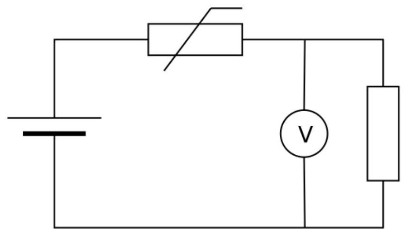
(2011-12) Consider the circuit below. Explain what happens to the reading on the voltmeter as the temperature increases (i.e. state what happens and explain why).

figure
Show worked solution
Behaviour As the temperature increases, the voltmeter reading decreases. Why The component labeled thermistor is an NTC thermistor, so when its temperature rises its resistance falls. The thermistor and the fixed resistor are in series across the supply, so they form a potential divider and the supply voltage is shared between them in proportion to their resistances. The potential difference across the thermistor (the voltmeter is connected in parallel with it) is therefore $$ V_{\text{therm}}=V_s\frac{R_{\text{therm}}}{R_{\text{fixed}}+R_{\text{therm}}} $$ As temperature increases, $R_{\text{therm}}$ decreases, so the fraction $\frac{R_{\text{therm}}}{R_{\text{fixed}}+R_{\text{therm}}}$ becomes smaller, meaning a smaller share of the supply voltage appears across the thermistor. Hence the voltmeter reading falls (while the remaining voltage drop across the fixed resistor increases).
2011-13C · Writtend4Mechanics and Energy · Archimedes principle — buoyancy and upthrust

(2011-13: Archimedes principle and Buoyancy) Archimedes principle is used to explain buoyancy and why things float. Archimedes principle states that any objects (such as a brick) immersed in a fluid (such as water) experiences an upthrust (U) equal to the weight of fluid displaced.

Upthrust = Weight of fluid displaced

(a) Consider a float, in the form of a cube, secured to the bottom of a deep pool of fresh water by a rope.

Length of each side $=20 \mathrm{~cm}$
Density of float material $=400 \mathrm{~kg} / \mathrm{m}^{3}$
Density of fresh water $=1000 \mathrm{~kg} / \mathrm{m}^{3}$
i. Calculate the weight of the float
ii. Calculate the weight of the water displaced
iii. Hence calculate the tension in the rope

(b) The rope now breaks. Calculate the initial acceleration of the float

(c) Sketch the velocity time graph for the float on the axes below. No scale is required on the velocity or time axes. Assume the pool is very deep and the float reaches terminal velocity before reaching the surface.

figure

(d) Consider the following acceleration-time graphs.

In each case add a scale to the acceleration axis and continue the graph until such time as the float has reached its terminal velocity. No scale is required on the time axis.
i. Sketch an acceleration-time graph for the float. Label this graph A
ii. Add a second line to show the acceleration-time graph for the same float immersed in salt water having a density of $1024 \mathrm{~kg} / \mathrm{m}^{3}$. Label this graph B
iii. Add a third line to show the acceleration-time graph, in fresh water, for a float made of the same material but having twice the dimensions i.e. a cube with sides of length 40 cm. Label this graph C

figure
Show worked solution
(a)

The cube has side $L=20\ \mathrm{cm}=0.20\ \mathrm{m}$, so its volume is $V=L^3=(0.20)^3=8.0\times 10^{-3}\ \mathrm{m^3}$. Its mass is $m=\rho_{\rm float}V=400(8.0\times10^{-3})=3.2\ \mathrm{kg}$. Its weight is therefore$$ W=mg=3.2(9.81)=31.4\ \mathrm{N} $$ When fully submerged, the displaced water volume equals the cube volume $V$, so the weight of displaced water (and hence the upthrust) is$$ U=\rho_{\rm water}Vg=1000(8.0\times10^{-3})(9.81)=78.5\ \mathrm{N} $$ The float is held at rest by the rope, so the net force is zero. Taking upward as positive, forces on the float are $U$ upward, and $W$ plus rope tension $T$ downward, so $U-W-T=0$, giving$$ T=U-W=78.5-31.4=47.1\ \mathrm{N} $$

(b)

Immediately after the rope breaks the float is still fully submerged and its speed is zero, so resistive drag is zero at that instant. The net upward force is then $F_{\rm net}=U-W=47.1\ \mathrm{N}$ and the mass is $m=3.2\ \mathrm{kg}$, so the initial acceleration is$$ a_0=\frac{F_{\rm net}}{m}=\frac{47.1}{3.2}=14.7\ \mathrm{m\,s^{-2}} $$ directed upward.

(c)

As the float rises, drag increases with speed and reduces the net upward force, so the acceleration decreases from its initial value until it becomes zero at terminal velocity. The velocity therefore increases from $0$ with a decreasing gradient, approaching a constant terminal velocity (horizontal line). A suitable qualitative sketch is: $$ \begin{tikzpicture}[x=1.0cm,y=1.0cm] \draw[->] (0,0) -- (8,0) node[right] {$t$}; \draw[->] (0,0) -- (0,4) node[above] {$v$}; \draw[thick] (0,0) .. controls (1,2.2) and (3,3.1) .. (7,3.3); \draw[dashed] (0,3.3) -- (7.6,3.3) node[right] {$v_{\rm t}$}; \end{tikzpicture} $$

(d)

The acceleration is initially positive because $U>W$, then as speed builds up the upward drag increases and reduces the net upward force, so the acceleration falls toward $0$ as terminal velocity is reached. For fresh water (graph A) the initial acceleration is the value from part (b), $a_{0A}=14.7\ \mathrm{m\,s^{-2}}$. For salt water (graph B) the upthrust is slightly larger because $\rho$ is larger, so the initial acceleration is slightly larger than A. For the larger cube (graph C) the initial acceleration is unchanged (because both upthrust and weight scale with volume), but its larger mass compared with its drag leads to a slower reduction of acceleration with time, so it stays above A for longer and reaches terminal velocity later. Numerical initial accelerations to set the acceleration-axis scale are$$ a_{0A}=\frac{(\rho_{\rm water}-\rho_{\rm float})}{\rho_{\rm float}}g=\frac{1000-400}{400}(9.81)=14.7\ \mathrm{m\,s^{-2}} $$ $$ a_{0B}=\frac{(\rho_{\rm salt}-\rho_{\rm float})}{\rho_{\rm float}}g=\frac{1024-400}{400}(9.81)=15.3\ \mathrm{m\,s^{-2}} $$ and for the $40\ \mathrm{cm}$ cube in fresh water $a_{0C}=a_{0A}=14.7\ \mathrm{m\,s^{-2}}$. A suitable qualitative sketch (with a scale on the acceleration axis) is: $$ \begin{tikzpicture}[x=1.0cm,y=0.25cm] \draw[->] (0,0) -- (8,0) node[right] {$t$}; \draw[->] (0,0) -- (0,18) node[above] {$a\ (\mathrm{m\,s^{-2}})$}; \draw (0,14.7) -- (0.2,14.7) node[left] {$14.7$}; \draw (0,15.3) -- (0.2,15.3) node[left] {$15.3$}; \draw (0,0) -- (0.2,0) node[left] {$0$}; \draw[thick,solid] (0,14.7) .. controls (1,10) and (3,4) .. (6,0.3) .. controls (6.5,0.1) and (7,0.0) .. (7.5,0.0) node[pos=0.35,right] {\textbf{A}}; \draw[thick,dashed] (0,15.3) .. controls (1,10.6) and (3.1,4.3) .. (6.1,0.35) .. controls (6.6,0.1) and (7.1,0.0) .. (7.6,0.0) node[pos=0.48,right] {\textbf{B}}; \draw[thick,dash dot] (0,14.7) .. controls (1,12) and (3.5,6) .. (7,0.4) .. controls (7.4,0.12) and (7.7,0.0) .. (7.9,0.0) node[pos=0.72,right] {\textbf{C}}; \end{tikzpicture} $$

2012-12B · Writtend2Mechanics and Energy · Electromagnetic induction — Faraday's law

(2012-12) Explain why an electrical transformer works using alternating current but does not work using direct current.

Show worked solution
Key physical principle A transformer transfers energy from the primary coil to the secondary coil through electromagnetic induction, which requires a changing magnetic flux linking the secondary coil. This is described by Faraday's law of induction: $$ \varepsilon_s = -N_s\frac{d\Phi_B}{dt} $$ where $\varepsilon_s$ is the induced emf in the secondary, $N_s$ is the number of turns on the secondary, and $\Phi_B$ is the magnetic flux through each turn (set by the core and the magnetic field produced by the primary current). Why alternating current works With alternating current, the primary current varies with time, so the magnetic field in the core varies with time, so the flux $\Phi_B(t)$ linking the secondary varies with time. That makes $\frac{d\Phi_B}{dt}\neq 0$ most of the time, so Faraday's law gives a nonzero induced emf in the secondary, producing a secondary voltage and allowing power transfer. In an ideal transformer the voltages are related to the turns ratio because the same changing flux links both coils, giving $$ \frac{V_s}{V_p}=\frac{N_s}{N_p} $$ which only has practical meaning when the induced emfs exist, i.e., when the flux is changing. Why direct current does not work (in steady operation) With direct current, after a brief switching-on transient the primary current becomes approximately constant, so the magnetic field in the core becomes approximately constant and the flux becomes constant. Then $\frac{d\Phi_B}{dt}=0$, so Faraday's law gives $\varepsilon_s=0$, meaning no sustained secondary voltage is induced and essentially no continuous power is transferred to the secondary. What happens at the moment DC is applied, and why that still does not make a transformer operate When DC is first connected, the primary current rises from $0$ to its steady value, so the flux changes briefly and a momentary emf can be induced in the secondary; however, once the current stops changing, the induced emf disappears. In addition, DC tends to drive the core toward magnetic saturation because the flux is pushed in one direction without reversing; saturation reduces the effective inductive reactance of the primary, causing a large current limited mainly by the winding resistance, leading to overheating and inefficiency rather than useful voltage transformation. Conclusion A transformer needs a time-varying magnetic flux to induce a secondary emf, which is naturally provided by alternating current; direct current produces zero induced secondary emf in steady state because it creates (approximately) constant flux, so a transformer does not work on DC except for a brief transient at switch-on.
2012-13C · Writtend3Mechanics and Energy · Energy and kinematics of a bouncing ball

(2012-13: Mechanics of a bouncing Rubber Ball) A rubber ball falls vertically and bounces on a hard floor. If the ball hits the floor at velocity v, it rebounds with a velocity 0.9v i.e. it rebounds with $90 \%$ of the impact velocity.

(a) The ball is dropped from a height of 1.0 m.

Using conservation of energy or otherwise, show that the velocity of the ball as it hits the floor for the first time is approximately $4.5 \mathrm{~m} / \mathrm{s}$.

(b) Calculate the maximum height the ball achieves after the first bounce.

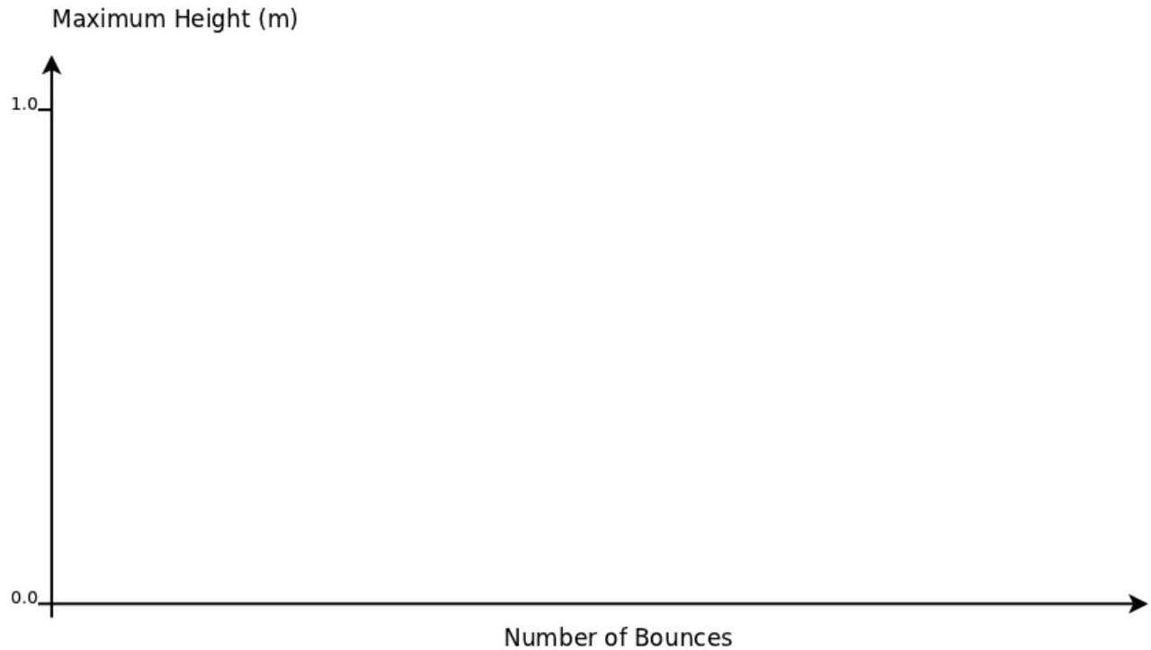
(c) Consider a graph of maximum height achieved after each successive bounce. Use the axes below to sketch the shape of the graph. No further calculations are expected.

figure

(d) Explain why the time between successive bounces decreases.

Show worked solution
(a)

As the ball falls from rest through height $h=1.0\,\mathrm{m}$, gravitational potential energy is converted into kinetic energy (neglect air resistance). Taking the floor as zero potential, the loss in potential energy $mgh$ becomes the gain in kinetic energy $\tfrac12 mv^2$ at impact, so $$ mgh=\frac12 mv^2 $$ The mass $m$ cancels, giving $$ v=\sqrt{2gh}=\sqrt{2(9.8)(1.0)}=\sqrt{19.6}=4.43\,\mathrm{m\,s^{-1}}\approx 4.5\,\mathrm{m\,s^{-1}} $$ so the impact speed is approximately $4.5\,\mathrm{m\,s^{-1}}$ as required.

(b)

The rebound speed is $0.9v$, so if the impact speed is $v\approx 4.43\,\mathrm{m\,s^{-1}}$, then the upward speed just after the bounce is $u=0.9v\approx 3.99\,\mathrm{m\,s^{-1}}$. During the rise after the bounce, kinetic energy is converted back into gravitational potential energy until the speed becomes zero at maximum height $H$, so $$ \frac12 mu^2=mgH $$ which gives $$ H=\frac{u^2}{2g}=\frac{(3.99)^2}{2(9.8)}=\frac{15.9}{19.6}=0.81\,\mathrm{m}\ \text{(to 2 s.f.)} $$ Therefore, the maximum height after the first bounce is $0.81\,\mathrm{m}$.

(c)

Each bounce reduces the speed immediately after impact by a factor $0.9$, so the maximum height after a bounce (which depends on $u^2$) is reduced by a factor $(0.9)^2=0.81$ each time. The plotted maximum heights therefore form a decreasing sequence that falls quickly at first and then levels off, approaching zero; the sketch should look like an exponential decay curve (or discrete points on such a curve) starting at $1.0\,\mathrm{m}$ and asymptotically tending toward $0$.

(d)

The time between bounces is the time to go up and come back down, and for vertical motion under gravity that flight time depends on the initial upward speed $u$ after the bounce. Since each bounce reduces $u$ by a factor $0.9$, the ball reaches a smaller height and also spends less time in the air. Quantitatively, the time to rise is $u/g$ and the time to fall back is the same, so the time between bounces is proportional to $u$ (specifically $2u/g$); because $u$ decreases after every bounce, the time between successive bounces decreases.

2013-12B · Writtend1Mechanics and Energy · Pressure and atmospheric pressure

(2013-12) Explain, in terms of pressure, how it is possible to use a drinking straw to drink from a glass of water.

Show worked solution
Pressure difference created by sucking

When you drink through a straw, you first reduce the air pressure inside your mouth and inside the straw by sucking. This means the pressure at the top of the straw becomes lower than the atmospheric pressure acting on the surface of the water in the glass.

Role of atmospheric pressure on the water surface

The water in the glass has atmospheric pressure pushing down on its surface, so the pressure at the water surface is approximately $P_{\text{atm}}$. If the pressure inside the straw at the top is $P_{\text{top}}$ and you have sucked so that $P_{\text{top}} < P_{\text{atm}}$, then there is a net upward push on the water in the straw because the pressure at the bottom (connected to the glass) is higher than the pressure at the top.

How the pressure difference supports a column of water

As water rises in the straw, it forms a vertical column of height $h$ above the water level in the glass. For the water column to be supported (and to rise until it reaches your mouth), the pressure difference must balance the hydrostatic pressure of that column:

$$ P_{\text{atm}} - P_{\text{top}} = \rho g h $$

Here $\rho$ is the density of water and $g$ is the gravitational field strength. This equation shows that the larger the pressure drop you create by sucking (the smaller $P_{\text{top}}$ becomes), the larger the height $h$ of water that can be lifted up the straw.

Key idea

The straw does not “pull” water up by suction as a force on the water itself; instead, sucking lowers the pressure in the straw, and the higher atmospheric pressure on the water surface in the glass pushes the water up into the region of lower pressure.

2013-14C · Writtend3Mechanics and Energy · Resistance, power dissipation, and heating

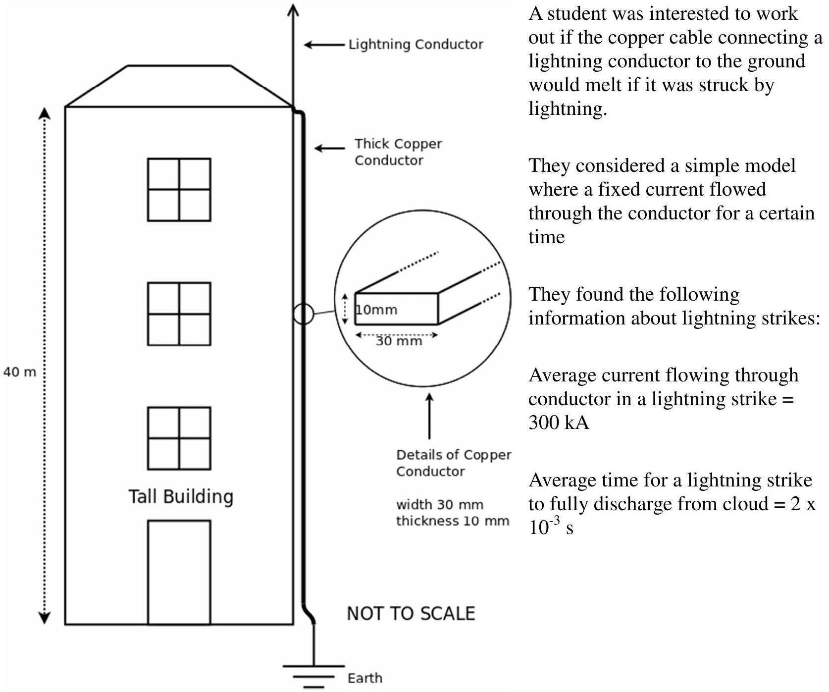
(2013-14: Analysis of a lightning strike (data analysis question)) This question asks you to use unfamiliar equations and concepts to solve a problem.
You will not have met some of the concepts in your normal physics course.
All of the information you need to solve the problem is given in the question.

figure

The students found the following useful data about the copper conductor:

Equation to calculate the resistance of a cable is $\mathrm{R}=\rho \mathrm{L} / \mathrm{A}$
( $\mathrm{R}=$ resistance, $\mathrm{L}=$ length, $\mathrm{A}=$ cross-sectional area and $\rho=$ constant called resistivity)
Resistivity of copper, $\rho=1.7 \times 10^{-8} \Omega \mathrm{~m}$
Specific heat capacity of copper $=385 \mathrm{~J} \mathrm{~kg}^{-1}{ }^{\circ} \mathrm{C}^{-1} \quad\left(\right.$ Energy needed to raise 1 kg by $1^{\circ} \mathrm{C}$ )
Density of copper $=8900 \mathrm{~kg} / \mathrm{m}^{3}$
Melting point of copper $=1085{ }^{\circ} \mathrm{C}$
a) Show that the resistance of the conductor is approximately $2 \mathrm{~m} \Omega$
For current flowing through a resistor we can use the equation, $\mathrm{P}=\mathrm{I}^{2} \mathrm{R}$ where $\mathrm{P}=$ Power, $\mathrm{I}=$ Current and $\mathrm{R}=$ Resistance
b) Calculate the power dissipated in the conductor and hence show that the energy transferred to the conductor is approximately 400 kJ
c) Calculate the mass of the thick copper conductor
d) Hence calculate the temperature rise experienced by the conductor and show that the conductor is unlikely to melt

Show worked solution
(a)

From the diagram the copper conductor has length $L=10\,m$ and diameter $d=10\,mm$, so the radius is $r=5.0\times 10^{-3}\,m$. The cross-sectional area is $$A=\pi r^2=\pi(5.0\times 10^{-3})^2=7.85\times 10^{-5}\,m^2$$ Using $R=\rho L/A$ with $\rho=1.7\times 10^{-8}\,\Omega m$, $$R=\frac{\rho L}{A}=\frac{(1.7\times 10^{-8})(10)}{7.85\times 10^{-5}}=2.17\times 10^{-3}\,\Omega\approx 2\,m\Omega$$ so the resistance is approximately $2\,m\Omega$ as required.

(b)

The lightning current in the diagram is $I=2.0\times 10^{4}\,A$ and it lasts for $t=0.50\,s$. The electrical power converted to thermal energy in a resistor is given by $P=I^2R$, so $$P=I^2R=(2.0\times 10^{4})^2(2.0\times 10^{-3})=8.0\times 10^{5}\,W$$ The energy transferred (electrical energy dissipated as heating) is $E=Pt$, hence $$E=Pt=(8.0\times 10^{5})(0.50)=4.0\times 10^{5}\,J=400\,kJ$$ which shows the energy is approximately $400\,kJ$.

(c)

The mass is found from $m=\rho_{\text{density}}V$, and the volume of the conductor is $V=AL$. Using $A=7.85\times 10^{-5}\,m^2$, $L=10\,m$, and copper density $=8900\,kg\,m^{-3}$, $$V=AL=(7.85\times 10^{-5})(10)=7.85\times 10^{-4}\,m^3$$ $$m=(8900)(7.85\times 10^{-4})=6.99\,kg\approx 7.0\,kg$$

(d)

The temperature rise comes from the heating equation $E=mc\Delta T$, where $c=385\,J\,kg^{-1}\,^{\circ}C^{-1}$ for copper. Using $E=4.0\times 10^{5}\,J$ and $m\approx 7.0\,kg$, $$\Delta T=\frac{E}{mc}=\frac{4.0\times 10^{5}}{(7.0)(385)}=1.48\times 10^{2}\,^{\circ}C\approx 150\,^{\circ}C$$ A rise of about $150\,^{\circ}C$ would leave the copper far below its melting point of $1085\,^{\circ}C$ (even starting from room temperature), so the conductor is unlikely to melt.

2014-11B · Writtend2Mechanics and Energy · Friction on an inclined plane

(2014-11) For a heavy block resting on a rough slope.

For small angles, there is a friction force preventing the block from sliding down the slope.

The angle of the slope is increased and, at one particular angle, the block begins to slide down the slope.

Explain why the block begins to slide when the angle is increased.

Show worked solution
Solution

A block on a rough slope experiences three main forces: its weight $mg$ acting vertically downward, the normal contact force $N$ perpendicular to the slope, and the friction force $f$ along the slope opposing any relative motion. Resolving the weight into components relative to the slope gives a downslope component $mg\sin\theta$ and a perpendicular component $mg\cos\theta$. The perpendicular component is balanced by the normal reaction, so $N=mg\cos\theta$, while the downslope component tends to make the block slide.

Static friction is the type of friction that acts when there is no slipping. It is a self-adjusting force: it increases as needed to oppose the tendency to slide, but it cannot exceed a maximum value. The maximum possible static friction is proportional to the normal force:

$$ f_{s,\max}=\mu_s N $$

For small $\theta$, the required friction to prevent slipping is $f=mg\sin\theta$, and this is less than or equal to the maximum available static friction. In that case the block can remain at rest because static friction can match the needed value.

As $\theta$ increases, the downslope component $mg\sin\theta$ increases, meaning a larger friction force is required to keep the block stationary. At the same time, the normal force $N=mg\cos\theta$ decreases as $\theta$ increases, so the maximum available static friction $f_{s,\max}=\mu_s N=\mu_s mg\cos\theta$ decreases. Therefore, increasing the angle both increases the driving force down the slope and reduces the maximum resisting friction.

Sliding begins at the critical angle where the required friction equals the maximum static friction:

$$ mg\sin\theta=\mu_s mg\cos\theta $$

Beyond this angle, $mg\sin\theta>\mu_s mg\cos\theta$, so static friction is no longer large enough to balance the downslope component of weight. The forces along the slope are then unbalanced, giving a net force down the slope, so the block accelerates and starts to slide.

2014-13C · Writtend4Mechanics and Energy · Kinematics from velocity–time graph

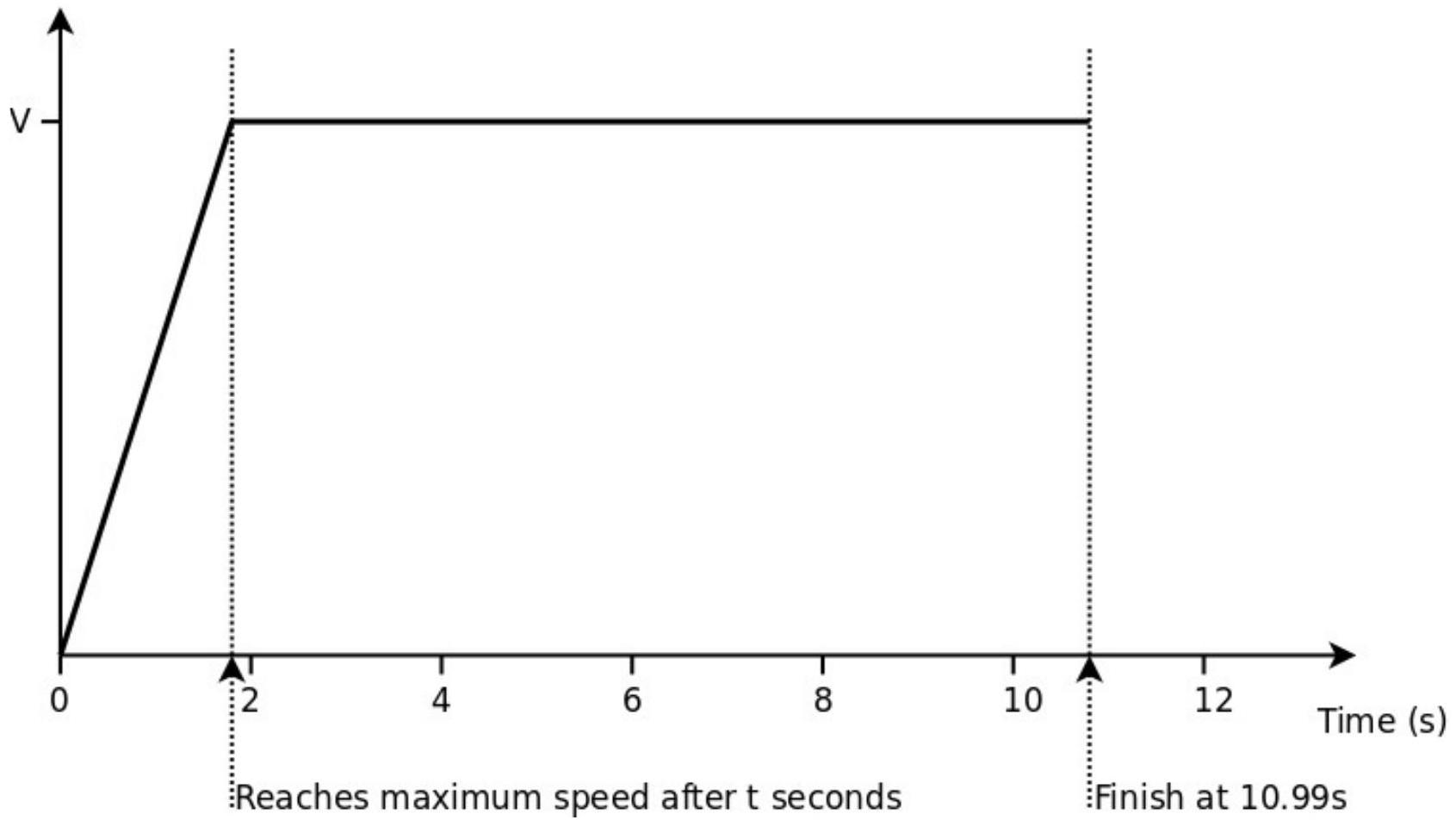
(2014-13: In this question you are asked to consider the effect of wind speed on the timing of a sprinter in a 100 m race.) If a following wind is present, it will provide a small extra force, helping the sprinter to accelerate.

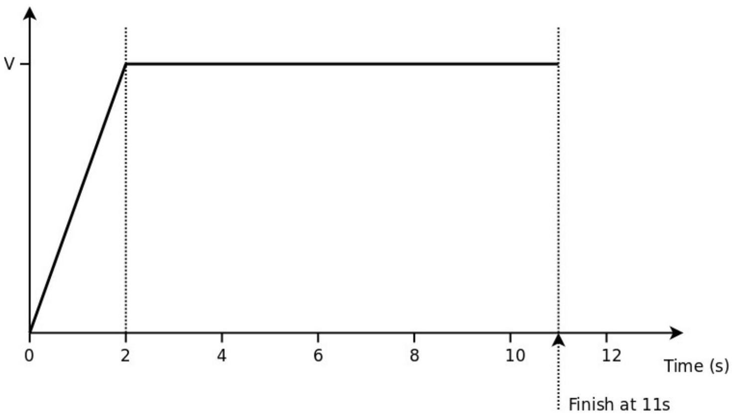
With no following wind, a very simplified graph of a 100 m sprint is shown below.

figure

(a) Use the graph to show $\mathrm{v}=10 \mathrm{~m} / \mathrm{s}$
(b) Calculate the resultant force acting on the sprinter when they are accelerating given that they have a mass of 70 kg .
With a following wind the sprinter achieves the same maximum speed of $10 \mathrm{~m} / \mathrm{s}$ but has a slightly greater acceleration and reaches maximum speed after only t seconds (where $t$ is slightly less than 2 seconds).
The following wind reduces the time to complete the race by 10 milliseconds (ms) as shown on the graph below.

figure

(c) Using the graph or otherwise, calculate the time ( t ) taken to reach maximum speed.
(d) Hence calculate the extra resultant force required to decrease the time of the race by 10 ms
The extra force on the runner can be roughly approximated as $F=0.7 \mathrm{u}^{2}$ where $u$ is the wind speed in $\mathrm{m} / \mathrm{s}$
(e) Hence calculate the wind speed that would give the 10 ms advantage.
(f) In reality a following wind has much less effect on the recorded time.

State and explain one reason why the approximation is not valid.

Show worked solution
(a)

From the speed--time graph the runner accelerates uniformly from $0$ to a constant maximum speed $v$ in $2\,\mathrm{s}$, then runs at this constant speed until the finish at $11\,\mathrm{s}$. The distance is the area under the graph, so $$ 100=\frac12(2)v+v(11-2)=v+9v=10v $$ $$ v=\frac{100}{10}=10\,\mathrm{m\,s^{-1}} $$

(b)

During the acceleration phase the acceleration is the gradient of the straight-line section: $$ a=\frac{\Delta v}{\Delta t}=\frac{10-0}{2-0}=5\,\mathrm{m\,s^{-2}} $$ The resultant force is $F=ma$: $$ F=70\times 5=350\,\mathrm{N} $$

(c)

With the wind, the runner still reaches the same maximum speed $10\,\mathrm{m\,s^{-1}}$, but reaches it after $t\,\mathrm{s}$ and finishes $10\,\mathrm{ms}=0.010\,\mathrm{s}$ sooner. The original time is $11.00\,\mathrm{s}$, so the new total time is $10.99\,\mathrm{s}$. Using area under the speed--time graph equals $100\,\mathrm{m}$: $$ 100=\frac12(t)(10)+10(10.99-t) $$ $$ 100=5t+109.9-10t=109.9-5t $$ $$ 5t=9.9 \;\;\Rightarrow\;\; t=1.98\,\mathrm{s} $$

(d)

The new acceleration (still assuming uniform acceleration to $10\,\mathrm{m\,s^{-1}}$) is $$ a'=\frac{10}{1.98}=5.05\,\mathrm{m\,s^{-2}} $$ So the new resultant force while accelerating is $$ F'=70a'=70\times 5.05=3.54\times 10^{2}\,\mathrm{N}\approx 354\,\mathrm{N} $$ The extra resultant force needed is $$ \Delta F=F'-F\approx 354-350=3.5\,\mathrm{N} $$

(e)

Using the approximation for the extra force from the wind, $F=0.7u^{2}$, with $F=\Delta F=3.5\,\mathrm{N}$: $$ 3.5=0.7u^{2}\;\;\Rightarrow\;\;u^{2}=5.0\;\;\Rightarrow\;\;u=\sqrt{5.0}=2.24\,\mathrm{m\,s^{-1}} $$ So a wind speed of about $2.2\,\mathrm{m\,s^{-1}}$ gives a $10\,\mathrm{ms}$ advantage.

(f)

The approximation treats the wind effect as a constant extra forward force depending only on $u$, but in reality the main effect of a tailwind is to reduce air resistance, and aerodynamic drag depends on the relative air speed, roughly proportional to $(v-u)^{2}$. Since $v$ changes throughout the race, the change in drag (and therefore the net force and acceleration) is not constant, so $F=0.7u^{2}$ is not valid for the whole sprint.

2015-12B · Writtend2Mechanics and Energy · Apparent weight and Newton's second law

(2015-12) An elevator, going up, accelerates from rest for a few moments before continuing upwards at a constant velocity.

A person in the elevator experiences a sensation of being heavier for the few moments during which the elevator initially accelerates from rest.

Explain why the person feels heavier in this case.

Show worked solution
Explanation

When the elevator is accelerating upward, the person must also accelerate upward with the elevator. The only significant vertical forces on the person are the weight $mg$ downward and the normal reaction force $N$ from the floor upward. The sensation of “heaviness” is tied to $N$ (the support force the floor exerts on the person), not directly to $mg$.

Taking upward as positive and applying Newton’s second law to the person during the upward acceleration $a$ gives $$ \sum F_y = ma \quad \Rightarrow \quad N - mg = ma $$ so the normal force is $$ N = mg + ma = m(g+a) $$ Because $a>0$ during the initial upward acceleration, $N>mg$. This means the floor must push up on the person with a force larger than their weight in order to produce the required upward acceleration. The person feels heavier because their apparent weight (the normal force $N$ they feel through their feet) is greater than their true weight $mg$.

Once the elevator moves upward at constant velocity, the acceleration becomes $a=0$, so $$ N = mg $$ and the sensation of extra heaviness disappears.

2015-13C · Writtend5Mechanics and Energy · Speed of light measurement — rotating mirror

(2015-13: Measuring the Speed of Light)

A method to make a direct measurement of the speed of light using a rotating mirror was originally developed by Leon Foucault who published his results in 1862. The method was later refined by Albert Michelson in 1926.

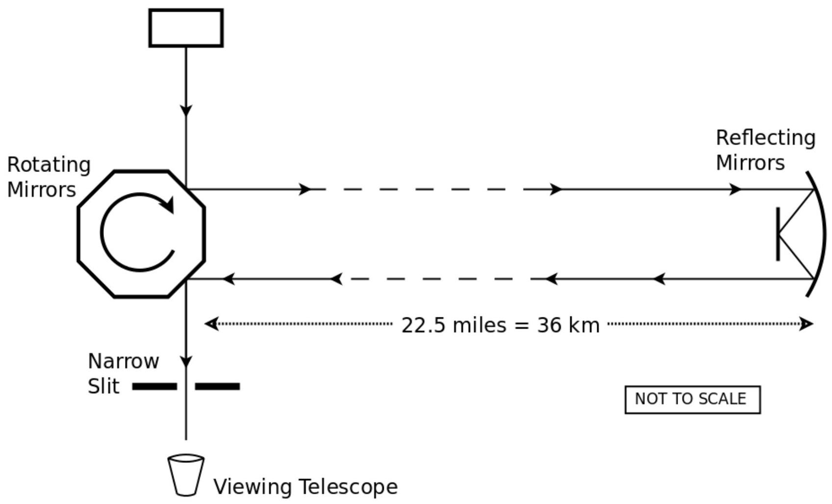
A simplified diagram of the apparatus is shown below.

figure

A narrow light beam from the source was reflected off one face of the rotating mirror, travelled to an adjacent mountain top 36 km away and returned to be observed through the telescope, as shown.

The mirror's rate of rotation was slowly increased from rest. At very specific rates of rotation an image of the light source became visible in the viewing telescope.

(a)(i) Explain why the light source can only be seen at very specific rates of rotation. (a)(ii) What is the minimum angle of rotation of the mirror so that the light source can be observed in the viewing telescope? (a)(iii) The minimum rate of rotation to allow the light source to be observed was found to be 31,000 rpm (revolutions per minute). Use this information to calculate the speed of light.

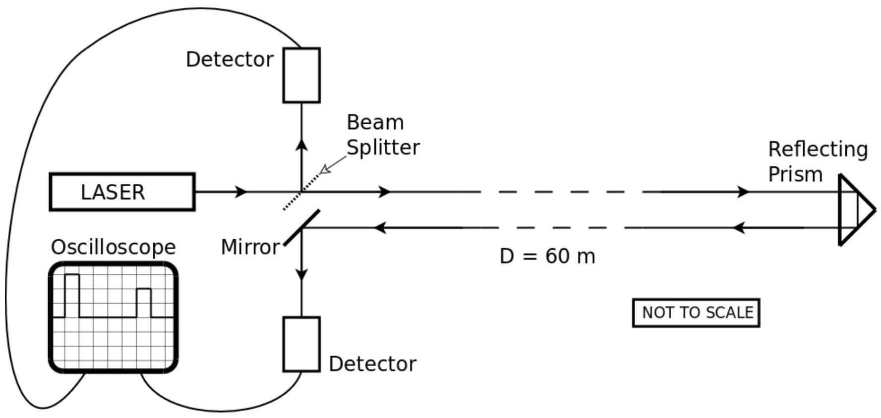
A student tries to measure the speed of light directly in the school laboratory. They use a laser beam that is modulated at a frequency of 1 MHz so that the beam produces $1 \times 10^{6}$ short pulses per second. The beam is split so that one beam goes directly to a detector and the other beam goes via a 60 m long corridor, is reflected and travels back down the corridor to a second mirror and detector.

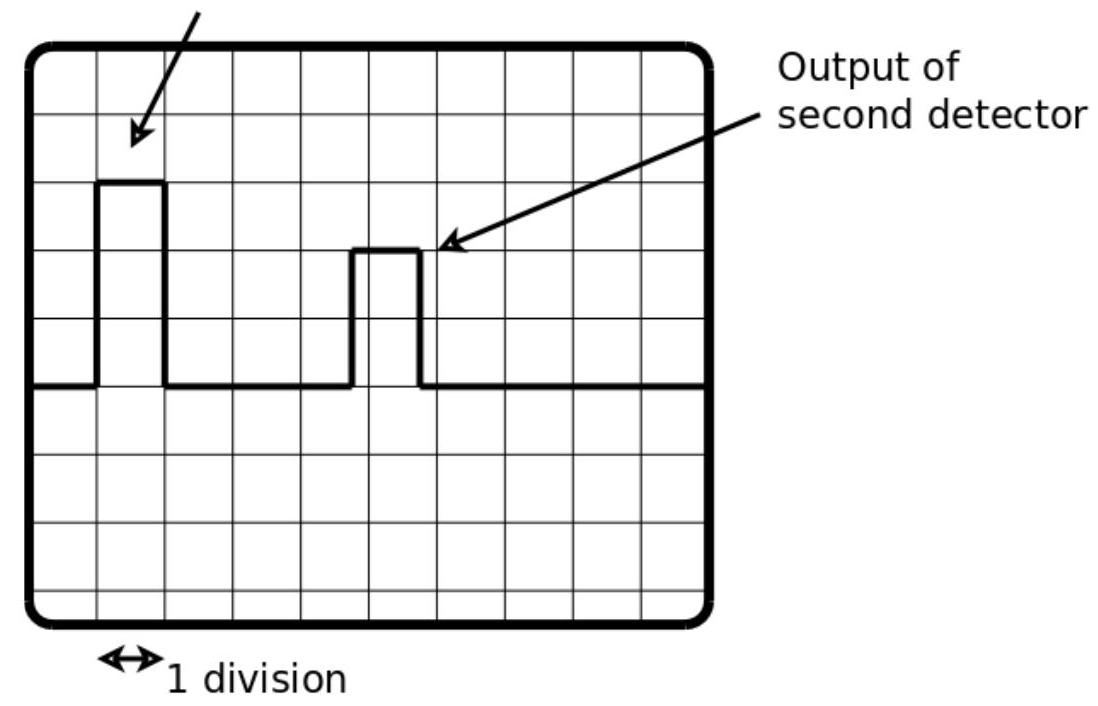
The outputs of the two detectors are combined and displayed on an oscilloscope screen.

figure

The timebase on the oscilloscope is set to $0.1 \mu \mathrm{s}$ per division.

figure

One big square is one division. Horizontally, one division is $0.1 \mu \mathrm{s}$ ($1 \mu \mathrm{s} = 1 \times 10^{-6}$ s). The vertical axis measures voltage.

The oscilloscope display shows the pulse arriving from the first detector and then the pulse from the second detector arriving some time later.

(b)(i) Use the information on the diagrams to calculate the speed of light as measured by the student. (b)(ii) Explain why the return signal has produced a smaller peak on the oscilloscope display.

The student decides that the value obtained for the speed of light is not very good and repeats the experiment using different distances (D) along the corridor.

The results are shown in the table:

$\mathrm{D} / \mathrm{m}$$\mathrm{t} / \mu \mathrm{s}$
300.3
450.4
60
750.6
900.7
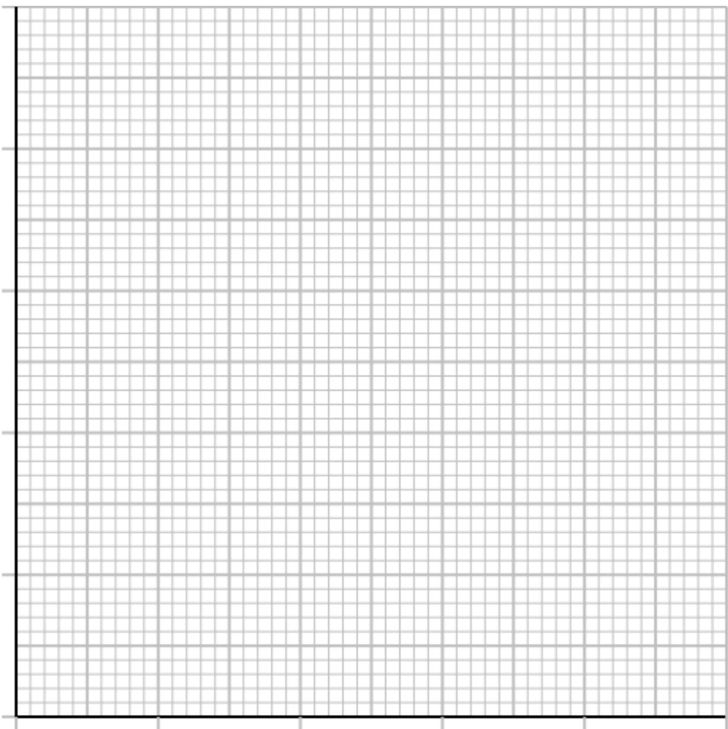
(c)(i) Plot a graph of the results.
figure
(c)(ii) The student realises that the detectors are giving a systematic error. Explain how the graph shows this and state the effect of the systematic error on the result obtained for (b). (c)(iii) Using the graph, or otherwise, determine a value for the speed of light for these results.

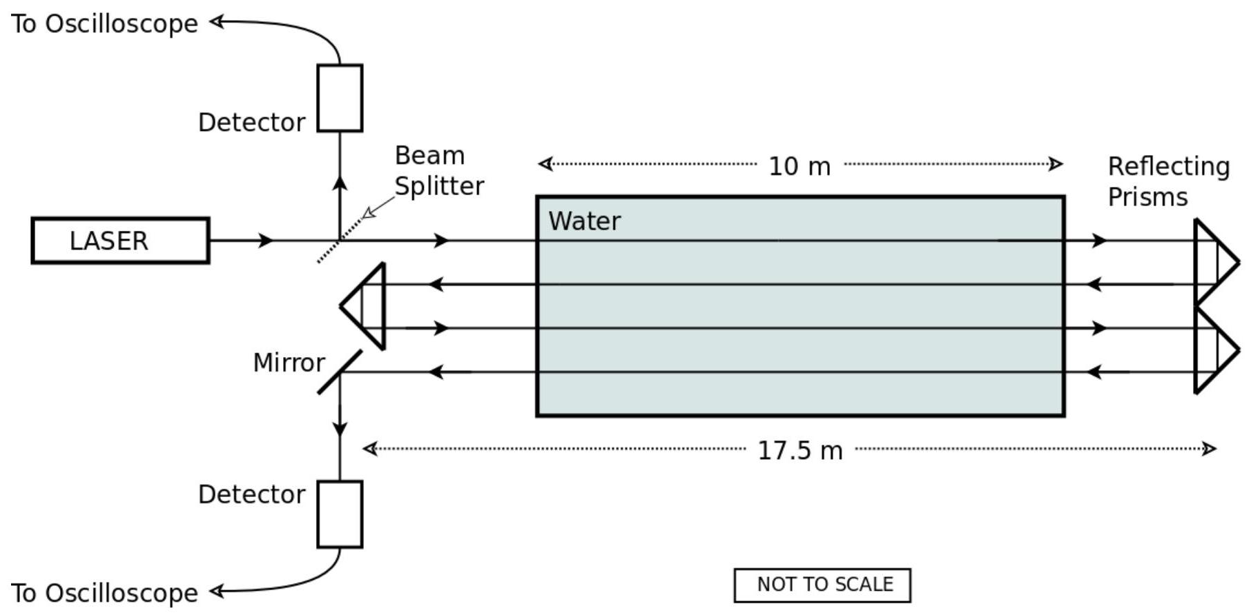
The student now tries to determine the speed of light in water by bouncing the light beam several times through a water tank as shown in the diagram below.

figure

The student uses the same detectors and the settings on the oscilloscope remain unchanged. The water tank is 10 m long, the distance between the reflecting prisms is 17.5 m.

figure
(d) Using the results shown on the oscilloscope trace and the results from part (c), determine the speed of light in water.

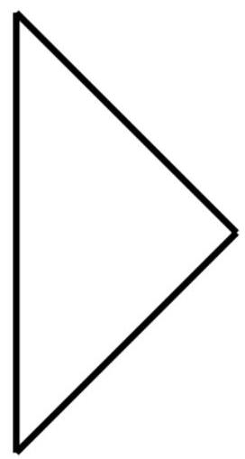
In the original Michelson experiment a mirror was used to reflect the light. In the laboratory based experiment, the student used prisms to return the light beam along the corridor.

(e)(i) Explain how the prism is used to 'reflect' the light beam. You may add to the diagram of the prism to help explain your answer.
figure
(e)(ii) Describe the advantage of using a prism instead of a mirror to reflect the beam. (e)(iii) By making suitable numerical estimates or suggesting likely values, explain why the reduction of the speed of light in the glass of the prisms is unlikely to have any measurable effect on the results obtained by the student.
Show worked solution
(a)(i)
The light leaves the source, reflects off one face of the rotating multi-faceted mirror, travels to the distant reflector and returns to the rotating mirror after a fixed flight time $t$. During this time the mirror continues to rotate, so when the returning beam arrives it will, in general, strike a face that is not oriented correctly to send the light into the viewing telescope; therefore no image is seen. An image is seen only when, at the instant the light returns, the mirror has rotated so that one of its faces is at exactly the required orientation to reflect the returning beam into the telescope aperture; since the mirror has discrete faces, this occurs only at very specific rotation rates (and their multiples). (a)(ii)
From the (Michelson/Foucault-style) rotating mirror used here, the first (minimum) condition for the returning beam to be directed into the telescope is that, during the round trip, the mirror turns so that the next face takes over, i.e. the mirror rotates by the angle between adjacent faces. The diagram corresponds to an 8-sided rotating mirror, so the minimum angle is $$ \Delta \theta_{\min}=\frac{360^\circ}{8}=45^\circ=\frac{\pi}{4}\ \text{rad}. $$ (a)(iii)
One-way distance to the mountain is $d=36\,\text{km}=3.6\times 10^4\ \text{m}$, so the round-trip distance is $2d=7.2\times 10^4\ \text{m}$. The minimum rotation rate is $31{,}000\ \text{rpm}$, i.e. $$ f=\frac{31{,}000}{60}=5.1667\times 10^2\ \text{s}^{-1},\qquad \omega=2\pi f=2\pi(5.1667\times 10^2)=3.246\times 10^3\ \text{rad s}^{-1}. $$ The light round-trip time equals the time for the mirror to rotate by $\Delta\theta_{\min}$: $$ t=\frac{\Delta\theta_{\min}}{\omega}=\frac{\pi/4}{3.246\times 10^3}=2.42\times 10^{-4}\ \text{s}. $$ Hence $$ c=\frac{2d}{t}=\frac{7.2\times 10^4}{2.42\times 10^{-4}}=3.0\times 10^8\ \text{m s}^{-1}. $$ (b)(i)
For $D=60\ \text{m}$ down the corridor, the pulse travels to the end and back, so the optical path is $2D=120\ \text{m}$. From the oscilloscope trace (timebase $0.1\ \mu\text{s}$ per division), the second pulse arrives $5$ divisions after the first, so $\Delta t=0.5\ \mu\text{s}=0.5\times 10^{-6}\ \text{s}$. Therefore $$ c_{\text{meas}}=\frac{2D}{\Delta t}=\frac{120}{0.5\times 10^{-6}}=2.4\times 10^8\ \text{m s}^{-1}. $$ (b)(ii)
The return signal peak is smaller because the returning beam has much lower intensity at the detector: it undergoes beam spreading (divergence), losses at the beam splitter, imperfect reflection/absorption losses at reflecting surfaces, and some misalignment/finite detector area losses, so the detector receives less optical power and produces a smaller voltage peak. (c)(i)
First complete the missing value using the clear linear trend in the table: for $D=60\ \text{m}$, $t=0.5\ \mu\text{s}$. Plot $t$ (vertical axis, in $\mu\text{s}$) against $D$ (horizontal axis, in m) using points $(30,0.3)$, $(45,0.4)$, $(60,0.5)$, $(75,0.6)$, $(90,0.7)$ and draw a best-fit straight line. (c)(ii)
A systematic error is shown because the best-fit straight line does not pass through the origin: extrapolating to $D=0$ gives a non-zero intercept time (about $0.1\ \mu\text{s}$). This indicates a fixed delay due to electronics (detector response time, cable delays, trigger delays, etc.). In part (b), this makes the measured time $\Delta t$ too large, so $c=2D/\Delta t$ is underestimated (the student's value is too small). (c)(iii)
Using $t=\dfrac{2D}{c}+t_0$, the gradient of the $t$--$D$ graph is $\dfrac{dt}{dD}=\dfrac{2}{c}$. From the plotted points, the gradient is $$ m=\frac{0.7-0.3}{90-30}=\frac{0.4}{60}=6.67\times 10^{-3}\ \mu\text{s m}^{-1}=6.67\times 10^{-9}\ \text{s m}^{-1}. $$ Hence $$ c=\frac{2}{m}=\frac{2}{6.67\times 10^{-9}}=3.0\times 10^8\ \text{m s}^{-1}. $$ (d)
From part (c), the systematic (fixed) delay is the intercept $t_0\approx 0.1\ \mu\text{s}$. From the oscilloscope trace for the water-tank arrangement, the measured delay between the reference pulse and the returned pulse is $t_{\text{meas}}=0.8\ \mu\text{s}$, so the true propagation time is $t_{\text{prop}}=t_{\text{meas}}-t_0=0.7\ \mu\text{s}$. From the diagram of the "multiple-bounce" path, the beam travels between the prisms in 10 straight passes; each pass is $17.5\ \text{m}$ long and contains $10\ \text{m}$ of water and $7.5\ \text{m}$ of air, so the total distances are $L_w=10\times 10=100\ \text{m}$ in water and $L_a=10\times 7.5=75\ \text{m}$ in air. Taking $c\approx 3.0\times 10^8\ \text{m s}^{-1}$ for air, the air time is $t_a=L_a/c=75/(3.0\times 10^8)=2.5\times 10^{-7}\ \text{s}=0.25\ \mu\text{s}$, so the water time is $t_w=t_{\text{prop}}-t_a=0.70-0.25=0.45\ \mu\text{s}=0.45\times 10^{-6}\ \text{s}$. Therefore $$ v_{\text{water}}=\frac{L_w}{t_w}=\frac{100}{0.45\times 10^{-6}}=2.2\times 10^8\ \text{m s}^{-1}. $$ (e)(i)
The prism "reflects" the beam by total internal reflection (TIR): the beam enters the glass, strikes an internal face at an incidence angle greater than the critical angle, and is totally reflected with essentially no transmission loss; after one or more such internal reflections (depending on prism geometry, e.g. right-angle prism or corner-cube/retroreflector), the beam emerges redirected back along (or parallel to) the corridor. The essential condition is $\theta_i>\theta_c$ where $\sin\theta_c=n_{\text{air}}/n_{\text{glass}}$, so for typical glass the critical angle is small enough that the internal incidence angles used are above $\theta_c$, guaranteeing TIR. (e)(ii)
A key advantage of a (retroreflecting) prism over a mirror is that the returned beam direction is much less sensitive to small misalignments: a corner-cube-type prism sends light back parallel (often back along the same path) over a range of orientations, making the experiment easier to align and more stable, and TIR also gives high reflectivity without needing a reflective coating. (e)(iii)
Any delay due to reduced speed in the prism glass is negligible because the glass path length is very small. For an estimate, take a generous total glass path length $L_g\sim 5\ \text{cm}=5\times 10^{-2}\ \text{m}$ and $n_{\text{glass}}\sim 1.5$, so the extra time compared with the same distance in air is approximately $$ \Delta t\approx \frac{n_{\text{glass}}L_g}{c}-\frac{L_g}{c}=\frac{(n_{\text{glass}}-1)L_g}{c}\approx \frac{0.5(5\times 10^{-2})}{3\times 10^8}\approx 8\times 10^{-11}\ \text{s}=0.08\ \text{ns}. $$ This is vastly smaller than the oscilloscope's horizontal scale ($0.1\ \mu\text{s}=10^5\ \text{ns}$ per division), so the prism-glass slowdown cannot produce a measurable shift in the student's timing results.
2016-12B · Writtend3Mechanics and Energy · NTC thermistor thermal runaway

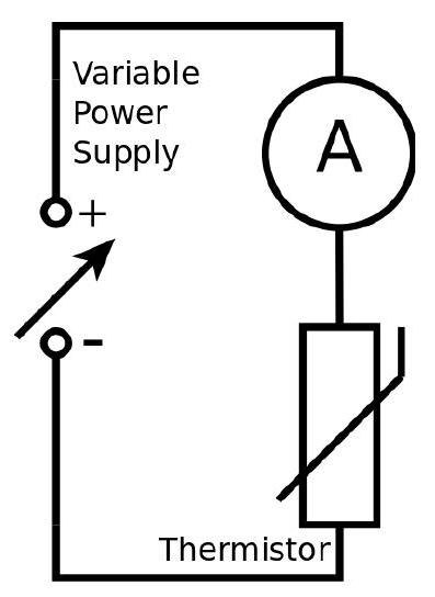
(2016-12) The electrical properties of a thermistor are investigated using the circuit shown:

figure
  • At low voltages, the current increases as the voltage increases
  • As the voltage is increased further, the current starts to rise more rapidly
  • At a certain voltage the current continues to increase even though the supply voltage remains constant
  • After a short time, with the same constant supply voltage, the current increases very rapidly and the thermistor is destroyed

Explain these observations.

Show worked solution
Explanation of the observations

At low voltages the thermistor remains close to room temperature, so its resistance is approximately constant. In this region it behaves nearly like an ohmic resistor, so increasing the potential difference across it produces a proportional increase in current, consistent with $I \approx V/R$.

As the voltage is increased further, the current becomes large enough that the thermistor dissipates significant electrical power. The heating power is $$ P = IV = I^2R = \frac{V^2}{R} $$ This power raises the thermistor temperature. For a typical thermistor used in such experiments (an NTC thermistor), the resistance decreases as temperature increases. A common approximate model is $$ R(T)=R_0\,e^{B\left(\frac{1}{T}-\frac{1}{T_0}\right)} $$ so as $T$ rises, $R$ falls rapidly. Because $I=V/R$, a falling $R$ makes $I$ rise faster than it would if the resistance were constant, which explains why the $I$--$V$ characteristic becomes increasingly steep at higher voltages.

At a certain applied voltage, the supply voltage is held constant but the current continues to increase with time because the thermistor does not reach its final temperature instantly. Its temperature keeps rising for a short time due to thermal inertia, so its resistance keeps dropping; with $V$ fixed, $I=V/R$ therefore increases even though the voltage is unchanged. This is a transient approach toward a thermal equilibrium where electrical heating is balanced by heat loss to the surroundings.

Finally, if the voltage is high enough, the situation becomes unstable: a small rise in temperature causes a decrease in resistance, which increases the current, which increases the power $P=V^2/R$, which causes even more heating. This positive feedback is thermal runaway. The thermistor temperature then rises very rapidly, the resistance collapses, the current surges, and the device overheats and is destroyed (often by cracking, burning of the material, or failure of leads due to excessive temperature).

2016-14C · Writtend4Mechanics and Energy · Wave refraction and Snell's law

(2016-14: Ocean Waves) Ocean waves arrive at the beach roughly parallel to the shore line, even if they were not travelling parallel to the shore line when they were further out to sea.

This question is about why waves on the ocean change direction as they approach the beach. To a good approximation, the speed of waves in shallow water depends only on the depth of the water and the acceleration due to gravity. The equation is:

$$c = \sqrt{g \times d} \quad \text{where} \quad c = \text{wave speed} \quad d = \text{depth of water}$$

An investigation to verify this wave speed equation involved the following:

  • A ripple tank was used to generate waves
  • The time for the ripples to travel the length of the tank was recorded
  • The depth of the water was changed and the measurement repeated

Results: Length of ripple tank = 70 cm
Depth of water / cmAverage time to travel length of ripple tank / s
0.53.1
0.72.6
1.12.1
(a) Use these results to verify that the wave speed equation is reasonable. HINT: $c = \sqrt{g \times d}$ can be written as $c = \sqrt{g} \times \sqrt{d}$ (b) Calculate the speed of water waves when the depth of the water is 90 cm.

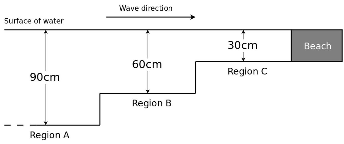
The diagram shows an idealised cross-section of an area of water approaching a beach. The water gets shallower in three steps and then ends at the beach. Waves travel from the left towards the beach.

figure

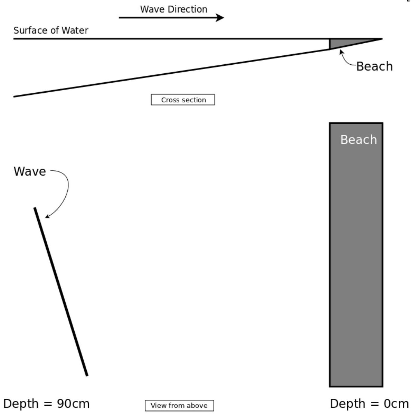
The same area of water is shown looking from above.

A wave is shown approaching the beach at an angle of $30^{\circ}$ to the shore line. As the wave crosses from Region A into Region B it changes direction. The directions are related to the wave speeds by the following equation:

$$\frac{\sin(\theta_A)}{\sin(\theta_B)} = \frac{c_A}{c_B}$$

where $\theta_A$ and $\theta_B$ are angles measured to the normal line and $c_A$ and $c_B$ are the speeds of the wave in Region A and Region B respectively.

(c)(i) On the diagram above, indicate:
  • The direction that the wave is travelling in Region A
  • The approximate direction that the wave will be travelling in Region B
(c)(ii) Calculate the direction of the wave in Region B relative to the shore line. (d) The waves enter Region A at a rate of one wave every 10 seconds. Determine the wavelength of the waves in Region A. (e) The diagram below shows the cross section, and the view from above, for a different section of water. The cross section is a more realistic gently sloping gradient where the depth changes gradually from 90 cm to zero as the waves approach the beach.

On the view from above, sketch the position and shape of the waves between the wave shown and the shore.

figure
Show worked solution
(a)

First calculate the wave speed $c$ from the measured time using $c=L/t$, with ripple tank length $L=70\ \mathrm{cm}=0.70\ \mathrm{m}$, and convert depths to metres. If the model $c=\sqrt{g}\sqrt{d}$ is correct, then the ratio $c/\sqrt{d}$ should be approximately constant and equal to $\sqrt{g}$. $$ c=\frac{L}{t} $$ Depth $0.5\ \mathrm{cm}=0.005\ \mathrm{m}$: $c=0.70/3.1=0.226\ \mathrm{m\,s^{-1}}$, $\sqrt{d}=\sqrt{0.005}=0.0707\ \mathrm{m^{1/2}}$, so $c/\sqrt{d}=0.226/0.0707=3.20\ \mathrm{m^{1/2}\,s^{-1}}$ Depth $0.7\ \mathrm{cm}=0.007\ \mathrm{m}$: $c=0.70/2.6=0.269\ \mathrm{m\,s^{-1}}$, $\sqrt{d}=\sqrt{0.007}=0.0837\ \mathrm{m^{1/2}}$, so $c/\sqrt{d}=0.269/0.0837=3.21\ \mathrm{m^{1/2}\,s^{-1}}$ Depth $1.1\ \mathrm{cm}=0.011\ \mathrm{m}$: $c=0.70/2.1=0.333\ \mathrm{m\,s^{-1}}$, $\sqrt{d}=\sqrt{0.011}=0.1049\ \mathrm{m^{1/2}}$, so $c/\sqrt{d}=0.333/0.1049=3.17\ \mathrm{m^{1/2}\,s^{-1}}$ These values are nearly constant and close to $\sqrt{g}=\sqrt{9.8}=3.13\ \mathrm{m^{1/2}\,s^{-1}}$, so the results support (verify as reasonable) the relationship $c=\sqrt{g\,d}$ within experimental uncertainty.

(b)

For depth $d=90\ \mathrm{cm}=0.90\ \mathrm{m}$, using $g=9.8\ \mathrm{m\,s^{-2}}$, $$ c=\sqrt{g\,d}=\sqrt{(9.8)(0.90)}=\sqrt{8.82}=2.97\ \mathrm{m\,s^{-1}} $$

(c)(i)

In Region A the wave travels toward the beach making $30^\circ$ to the shoreline (so it is slanted relative to the shore). When it enters the shallower Region B its speed decreases, so the wave refracts toward the normal (the direction becomes more directly toward the beach), meaning the angle to the normal gets smaller and the direction becomes closer to perpendicular to the shoreline.

(c)(ii)

From the cross-section, take Region A depth $d_A=90\ \mathrm{cm}=0.90\ \mathrm{m}$ and Region B depth $d_B=60\ \mathrm{cm}=0.60\ \mathrm{m}$, so $$ c_A=\sqrt{9.8\times 0.90}=2.97\ \mathrm{m\,s^{-1}},\qquad c_B=\sqrt{9.8\times 0.60}=2.43\ \mathrm{m\,s^{-1}} $$ The given $30^\circ$ is to the shoreline, so to the normal it is $\theta_A=90^\circ-30^\circ=60^\circ$. Using $$ \frac{\sin\theta_A}{\sin\theta_B}=\frac{c_A}{c_B}\ \Rightarrow\ \sin\theta_B=\sin\theta_A\frac{c_B}{c_A} $$ $$ \sin\theta_B=\sin 60^\circ\left(\frac{2.43}{2.97}\right)=(0.866)(0.818)=0.708\ \Rightarrow\ \theta_B\approx 45^\circ $$ $\theta_B$ is to the normal, so the direction relative to the shoreline is $90^\circ-\theta_B\approx 90^\circ-45^\circ=45^\circ$, meaning the wave in Region B travels at about $45^\circ$ to the shoreline (more straight in toward the beach than in Region A).

(d)

One wave every $10\ \mathrm{s}$ means the period is $T=10\ \mathrm{s}$, so the wavelength in Region A is $\lambda=c_A T$ with $c_A=2.97\ \mathrm{m\,s^{-1}}$: $$ \lambda=(2.97)(10)=29.7\ \mathrm{m}\approx 30\ \mathrm{m} $$

(e)

As the depth decreases gradually, the wave speed decreases gradually, so the part of each wavefront closer to the shore slows first and the wavefront bends smoothly (not in sharp kinks); on the plan view you should draw several wavefront lines between the given wave and the shore that progressively curve so that nearer the shore they become almost parallel to the shoreline, and the spacing between successive wavefronts decreases toward the shore because $\lambda=c/f$ and the frequency stays the same while $c$ decreases.

2017-11B · Writtend2Mechanics and Energy · Apparent weight and Newton's second law

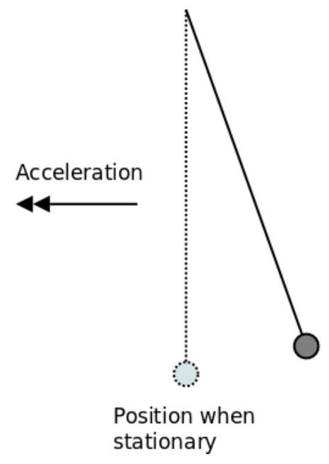
(2017-11) The following experiment was conducted to measure the acceleration of an aircraft as it accelerated down the runway:

  • A pendulum was allowed to hang freely inside the aircraft when it was stationary.
  • As the aircraft accelerated down the runway, the pendulum was observed to hang at an angle to the vertical as shown.
  • The angle of the pendulum was measured and used to calculate the acceleration.

The pendulum was made of a pendulum bob hung from a length of string.

figure

Position when stationary

Explain why the pendulum hung at an angle as shown while the aircraft was accelerating.

Show worked solution
Forces on the pendulum bob during acceleration

When the aircraft accelerates horizontally down the runway with acceleration $a$, the pendulum bob hangs at an angle $\theta$ to the vertical. There are two forces acting on the bob:

  • Its weight $W=mg$ acting vertically downward
  • The tension $T$ in the string acting along the string toward the point of suspension

Resolving forces and applying Newton's second law

Horizontally, the bob accelerates with the aircraft, so the horizontal component of the tension provides this accelerating force: $$ T\sin\theta=ma. $$

Vertically, the bob is in equilibrium (no vertical acceleration), so the vertical component of the tension balances the weight: $$ T\cos\theta=mg. $$

Dividing the horizontal equation by the vertical equation gives $$ \tan\theta=\frac{ma}{mg}=\frac{a}{g}. $$

Why the pendulum hangs at an angle

For the pendulum to hang vertically ($\theta=0$), we would need $a=0$ — i.e. the aircraft must be either stationary or moving at constant velocity. When the aircraft accelerates ($a>0$), the bob must swing backward so that the tension has a horizontal component to provide the accelerating force. The angle adjusts until $\tan\theta=a/g$. A larger acceleration requires a larger angle.

Energy interpretation

From the aircraft's non-inertial (accelerating) reference frame, there is an effective "gravitational" field $\vec{g}_{\text{eff}}=\vec{g}-\vec{a}$ pointing slightly backward and downward. The pendulum aligns itself with $\vec{g}_{\text{eff}}$, making an angle $\theta$ to the true vertical where $\tan\theta=a/g$.

2017-13C · Writtend4Mechanics and Energy · Escape velocity and orbital energy

(2017-13: From the Earth to the Moon) In his 1865 novel "From the Earth to the Moon" Jules Verne tells the story of a group of enthusiasts who attempt to build an enormous space gun to launch three people in a capsule with the goal of landing on the moon.

This question is about the feasibility of Jules Verne's ideas.

Note: In the following questions ignore all effects due to the rotation of the Earth, the position on Earth of the cannon and the effect of the atmosphere. (a) Rather than aiming for the Moon, consider using the cannon to shoot a 1000 kg capsule from the Earth's surface to an orbit equivalent to that of the International Space Station 330 km above the Earth's surface.

Assume that the acceleration due to gravity has a value of $10 \mathrm{~ms}^{-2}$ and does not change significantly up to a height of 330 km.

Show that the capsule must be shot from the surface of the Earth at a minimum velocity of approximately $2.5 \mathrm{~km} \mathrm{~s}^{-1}$.

(b) The acceleration due to gravity actually reduces with height above the Earth's surface and is less than $10 \mathrm{~ms}^{-2}$ at a height of 330 km.

Explain what affect this would have on the velocity calculated in part (a) above.

(c) As the capsule is fired along the cannon barrel it accelerates. The capsule can withstand a maximum constant acceleration of $a_{\max} = 100 \mathrm{~ms}^{-2}$.

Assume the capsule accelerates uniformly along the length of the barrel and achieves the velocity calculated in part (a) as it leaves the barrel of the cannon.

Sketch a velocity-time graph for the capsule inside the barrel of the cannon as it is accelerated from rest until the moment it leaves the cannon. Add appropriate values to each axis.

figure
(d) Using the graph, or otherwise, calculate the minimum length of the cannon. (e) Comment on the feasibility of shooting a space capsule from the Earth's surface using a large cannon as proposed by Jules Verne.

The velocity required for an object to completely escape from the gravitational field of the Earth, from the surface, is given by the equation:

$$v_{\text{escape}} = \sqrt{2gR}$$

where $R =$ radius of Earth and $g =$ gravitational field strength at the surface.

(f) Given that the radius of the Earth is 6400 km, calculate the escape velocity from the surface of the Earth.

The same equation for escape velocity can be applied to other similar objects in the solar system.

(g) Use the escape velocity equation to explain why: (i) It will probably be possible to simply shoot minerals mined from the asteroids in the asteroid belt back towards Earth. (ii) The Moon, small rocky planets and other moons have very little, if any, atmosphere.
Show worked solution
(a)

To reach a maximum height $h=330\,\mathrm{km}=3.3\times 10^{5}\,\mathrm{m}$ with the minimum launch speed, the capsule should arrive at that height with zero vertical speed, so the initial kinetic energy is converted into gravitational potential energy (with $g$ taken as constant): $$ \frac12 mv^2=mgh $$ The mass cancels, giving $$ v=\sqrt{2gh}=\sqrt{2(10)(3.3\times 10^{5})}=\sqrt{6.6\times 10^{6}}\approx 2.6\times 10^{3}\,\mathrm{m\,s^{-1}}\approx 2.5\,\mathrm{km\,s^{-1}} $$ So the capsule must be fired at a minimum speed of approximately $2.5\,\mathrm{km\,s^{-1}}$ to reach $330\,\mathrm{km}$ altitude (ignoring air resistance and Earth’s rotation).

(b)

If $g$ decreases with height, the increase in gravitational potential energy from the surface to $330\,\mathrm{km}$ is less than $mgh$ using $g=10\,\mathrm{m\,s^{-2}}$, so less initial kinetic energy is needed; therefore the true minimum launch speed would be slightly smaller than the value found in (a).

(c)

Inside the barrel the capsule starts from rest and accelerates uniformly at the maximum allowed constant acceleration $a_{\max}=100\,\mathrm{m\,s^{-2}}$, so the velocity increases linearly with time: $v=at$. Using the required exit speed $v\approx 2.5\,\mathrm{km\,s^{-1}}=2500\,\mathrm{m\,s^{-1}}$, the time taken in the barrel is $$ t=\frac{v}{a}=\frac{2500}{100}=25\,\mathrm{s} $$ The velocity--time graph is a straight line from $(0\,\mathrm{s},\,0\,\mathrm{m\,s^{-1}})$ to $(25\,\mathrm{s},\,2500\,\mathrm{m\,s^{-1}})$; the gradient is $100\,\mathrm{m\,s^{-2}}$. Label the horizontal axis $t$ in seconds from $0$ to $25$, and the vertical axis $v$ in $\mathrm{m\,s^{-1}}$ from $0$ to $2500$.

(d)

The distance travelled in the barrel equals the area under the velocity--time graph. For uniform acceleration this area is a triangle of base $t$ and height $v$: $$ s=\frac12 vt=\frac12 (2500)(25)=3.125\times 10^{4}\,\mathrm{m}\approx 3.1\times 10^{4}\,\mathrm{m}\approx 31\,\mathrm{km} $$ So the minimum cannon length is about $31\,\mathrm{km}$.

(e)

A barrel length of order $30\,\mathrm{km}$ is already impractical to construct and align, and even with the limited acceleration $100\,\mathrm{m\,s^{-2}}$ (about $10g$) the mechanical stresses on the capsule and gun would be enormous; in reality the capsule would also experience extreme atmospheric drag and heating on exiting the barrel at several $\mathrm{km\,s^{-1}}$, likely destroying it. In addition, reaching ISS-like orbit requires a large horizontal speed (around $7$--$8\,\mathrm{km\,s^{-1}}$) as well as altitude, so the true required launch speed would be much larger than in (a), making the cannon concept even less feasible.

(f)

With $R=6400\,\mathrm{km}=6.4\times 10^{6}\,\mathrm{m}$ and $g=10\,\mathrm{m\,s^{-2}}$, $$ v_{\text{escape}}=\sqrt{2gR}=\sqrt{2(10)(6.4\times 10^{6})}=\sqrt{1.28\times 10^{8}}\approx 1.13\times 10^{4}\,\mathrm{m\,s^{-1}}\approx 11.3\,\mathrm{km\,s^{-1}} $$ So the escape velocity from Earth’s surface is approximately $11.3\,\mathrm{km\,s^{-1}}$.

(g) (i) For an asteroid, both $R$ and $g$ are much smaller than for Earth, so from $v_{\text{escape}}=\sqrt{2gR}$ the escape velocity is very small (often only a few $\mathrm{m\,s^{-1}}$ to tens of $\mathrm{m\,s^{-1}}$). That means mined material does not need much launch speed to leave the asteroid permanently, so it should be possible to “shoot” minerals off the asteroid with relatively simple machinery compared with Earth. (ii) The Moon and other small rocky bodies also have small $g$ and $R$, hence small escape velocity. Gas molecules in an atmosphere have thermal speeds; when typical molecular speeds are a significant fraction of the escape velocity, molecules can readily escape to space over time (and are also more easily stripped by solar wind). Therefore small bodies cannot retain much gas, so they have very little atmosphere or none at all.
2018-12B · Writtend3Mechanics and Energy · Series circuit — brightness and power

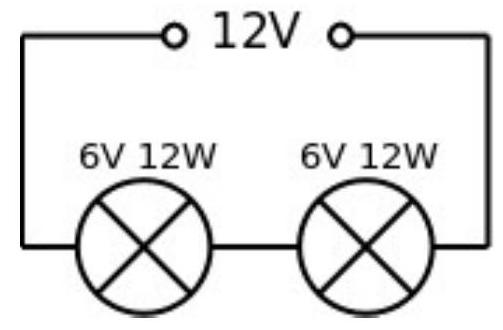
(2018-12) Two identical bulbs are rated at 6 V and 12 W.

They are connected in series to a 12 V power supply and are each lit to their normal brightness.

One of the bulbs breaks and is replaced by a bulb rated at 6 V and 24 W.

figure

In the new arrangement the bulbs are not the same brightness.

Explain why, in the new arrangement, the bulbs would not be the same brightness. State which bulb would be the brighter.

Show worked solution
The brightness of a filament bulb depends on the electrical power it dissipates, since (approximately) more power $\Rightarrow$ higher filament temperature $\Rightarrow$ more light output. The power depends on how the $12\ \mathrm{V}$ supply voltage is shared between the two series bulbs, which is determined by their resistances. From the ratings, the (hot, operating) resistance of each bulb can be estimated using $$ R=\frac{V^2}{P} $$ For the original identical bulbs ($6\ \mathrm{V},\,12\ \mathrm{W}$ each), $$ R_{12\mathrm{W}}=\frac{6^2}{12}=3\ \Omega $$ so two equal $3\ \Omega$ resistances in series share the $12\ \mathrm{V}$ equally, giving $6\ \mathrm{V}$ across each; therefore each dissipates its rated $12\ \mathrm{W}$ and they have the same normal brightness. When one bulb is replaced by a $6\ \mathrm{V},\,24\ \mathrm{W}$ bulb, its operating resistance is $$ R_{24\mathrm{W}}=\frac{6^2}{24}=1.5\ \Omega $$ so the series circuit now contains unequal resistances ($3\ \Omega$ and $1.5\ \Omega$). The series current becomes $$ I=\frac{12}{3+1.5}=2.67\ \mathrm{A} $$ and the voltage drops are $V_{12\mathrm{W}}=I(3)=8.0\ \mathrm{V}$ and $V_{24\mathrm{W}}=I(1.5)=4.0\ \mathrm{V}$, so the $12\ \mathrm{W}$ bulb is now over-voltaged while the $24\ \mathrm{W}$ bulb is under-voltaged. Their powers are therefore different: $$ P_{12\mathrm{W}}=I^2(3)=21.3\ \mathrm{W},\qquad P_{24\mathrm{W}}=I^2(1.5)=10.7\ \mathrm{W} $$ Hence they are not the same brightness because unequal resistances in series do not share the supply voltage equally, leading to different power dissipation; the $6\ \mathrm{V},\,12\ \mathrm{W}$ bulb dissipates more power and would be the brighter bulb.
2018-14C · Writtend5Mechanics and Energy · Power, energy, and Poiseuille flow

(2018-14: This question is about a moving walkway) Moving walkways are often found in airports and shopping centres. Consider a moving walkway with the following specifications:

  • Length $=60 \mathrm{~m}$
  • Normal speed $=1.5 \mathrm{~m} / \mathrm{s}$
  • Idle (energy saving) speed $=0.5 \mathrm{~m} / \mathrm{s}$
  • Mass of moving section of walkway $=8000 \mathrm{~kg}$
  • Friction force experienced by moving walkway $=2000 \mathrm{~N}$

Note: assume the frictional force is independent of the speed of the walkway, the number of passengers being carried, and remains constant.
a) Assuming that the only energy losses are due to work done against the frictional forces experienced by the moving walkway, show that the power required to keep the walkway moving at normal speed, but with no passengers, is 3 kW .
[0pt] [1 mark]
b) A group of passengers with a combined mass of 800 kg step on to, and stand still on, the walkway which is moving at normal speed. The passengers can be taken to be initially at rest and are then accelerated from rest by the walkway.

Theory: The energy expended by the walkway, in accelerating the passengers from rest, is twice the kinetic energy gained by the passengers.

Calculate the total energy expended transporting the passengers to the end of the walkway.
To save energy, the walkway runs at a lower idle speed when there are no passengers on the walkway. When a passenger approaches the walkway, the speed increases to the normal operating speed.
c) The same group of passengers, with a combined mass of 800 kg , approach the walkway when it is running at the lower idle speed, and the walkway responds by increasing to the normal operating speed. They then step on to the walkway in the same manner as in part (b). Assume the time taken to speed up is very small compared to the time taken for the passengers to reach the end of the walkway.

Calculate the total energy expended transporting the passengers to the end of the walkway.
d) Once the passengers have reached the end and stepped off the walkway, there is a delay before the runway slows down again.

Suggest and justify a suitable time delay, before the walkway slows down again, to make the walkway run as efficiently as possible.
15. Poiseuille was a French physicist and physiologist who was interested in blood flow through narrow tubes such as capillaries and veins. In 1838 he experimentally derived the relationship for the rate of flow of a fluid through a narrow tube. This is known as Poiseuille's Law ${ }^{* *}$.

This question is about experimentally verifying Poiseuille's Law
Poiseuille's Law for water flowing through a tube is: $\quad \frac{\Delta V}{\Delta t}=\frac{\pi r^{4} \Delta p}{8 \eta L}$
Where: $\quad \frac{\Delta V}{\Delta t}=$ volume of water flowing through the narrow tube per second (flow rate)
$r=$ internal radius of the narrow tube
$\Delta p=$ pressure difference between the ends of the narrow tube
$\eta=$ a constant called the viscosity (a measure of the resistance to flow)
$L=$ length of the narrow tube

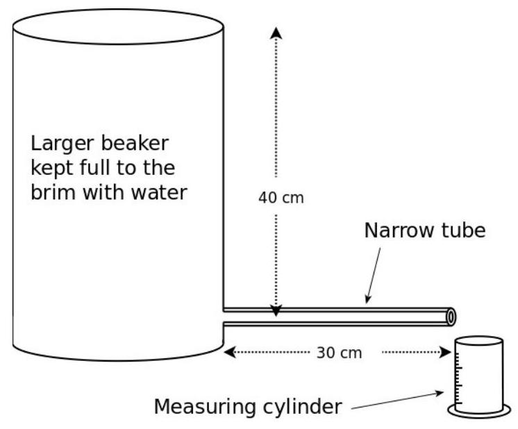
A student used the apparatus shown to measure the amount of water that flowed through a narrow tube in a minute. The water was collected in a small measuring cylinder. The large beaker of water was kept topped up throughout the experiment by adding more water as necessary.

In the experiment
$L=30 \mathrm{~cm} \quad$ (Length of narrow tube)
$r=0.5 \mathrm{~mm}$ (Internal diameter of narrow tube)
Density of the water $=1000 \mathrm{~kg} / \mathrm{m}^{3}$

figure

To verify Poiseuille's Law, $r$ was varied and $\frac{\Delta V}{\Delta t}$ was measured.
a) Show that the pressure at a depth of 40 cm due to the water in the large beaker is 4000 Pa .
b) Explain why atmospheric pressure does not affect the flow rate i.e. the amount of water flowing through the tube each second
c) Explain why the beaker of water must be constantly topped up to keep it full during the experiment.
d) The amount of water collected in 1 minute was $22 \mathrm{~cm}^{3}$. Calculate the rate of flow of water $\left(\frac{\Delta V}{\Delta t}\right)$ in units of cubic meters per second ( $\mathrm{m}^{3} / \mathrm{s}$ ).
e) Use Poiseuille's Law to show that $\eta \approx 9 \times 10^{-4} \mathrm{~Pa} \mathrm{~s}$
To verify the equation, the experiment was repeated with different narrow tubes, each 30 cm long but with different radii. The results are shown below:

Internal radius of the narrow tube $/ \mathrm{mm}$Volume of water collected in 1 minute $/ \mathrm{cm}^{3}$
0.33
0.522
0.784
1.0350

f) Discuss whether or not the results obtained support Poiseuille's Law

Show worked solution
(a)

The power needed to keep the walkway moving at constant speed is the rate of doing work against the constant friction force $F$, so $$P=Fv$$ With $F=2000\,\mathrm{N}$ and $v=1.5\,\mathrm{m\,s^{-1}}$, $$P=2000\times 1.5=3000\,\mathrm{W}=3.0\,\mathrm{kW}$$ so the required power is $3\,\mathrm{kW}$.

(b)

The energy used has two contributions: work done against friction while the passengers are being carried, and extra energy expended accelerating the passengers from rest to the walkway speed. The frictional work over the walkway length $L=60\,\mathrm{m}$ is $$W_f=FL=2000\times 60=1.20\times 10^{5}\,\mathrm{J}$$ The passengers (mass $m=800\,\mathrm{kg}$) reach speed $v=1.5\,\mathrm{m\,s^{-1}}$, gaining kinetic energy $$E_k=\frac12 mv^2=\frac12(800)(1.5)^2=900\,\mathrm{J}$$ The given theory states the walkway expends twice this energy in accelerating them, so $$E_{\text{acc,exp}}=2E_k=1800\,\mathrm{J}$$ Hence the total energy expended transporting the passengers to the end is $$E_{\text{total}}=W_f+E_{\text{acc,exp}}=1.20\times 10^{5}+1.8\times 10^{3}=1.218\times 10^{5}\,\mathrm{J}\approx 1.22\times 10^{5}\,\mathrm{J}$$

(c)

Compared with part (b), there is an additional energy cost: increasing the kinetic energy of the moving section of the walkway (mass $M=8000\,\mathrm{kg}$) from idle speed $u=0.5\,\mathrm{m\,s^{-1}}$ to normal speed $v=1.5\,\mathrm{m\,s^{-1}}$. The increase in kinetic energy is $$\Delta E_{\text{walkway}}=\frac12 M(v^2-u^2)=\frac12(8000)\bigl((1.5)^2-(0.5)^2\bigr)=4000(2.25-0.25)=8000\,\mathrm{J}$$ The time for speeding up is stated to be very small compared with the travel time, so the frictional work during the passengers’ journey is still essentially the work over $60\,\mathrm{m}$ at operating conditions, $$W_f=2000\times 60=1.20\times 10^{5}\,\mathrm{J}$$ The passengers are still accelerated from rest to $1.5\,\mathrm{m\,s^{-1}}$, so the expended acceleration energy is the same as in part (b), $1800\,\mathrm{J}$. Therefore $$E_{\text{total}}=W_f+E_{\text{acc,exp}}+\Delta E_{\text{walkway}}=1.20\times 10^{5}+1.8\times 10^{3}+8.0\times 10^{3}=1.298\times 10^{5}\,\mathrm{J}\approx 1.30\times 10^{5}\,\mathrm{J}$$

(d)

Running at normal speed wastes energy compared with idle speed because the friction power is larger: $$P=Fv$$ so $P_{\text{normal}}=2000(1.5)=3000\,\mathrm{W}$ and $P_{\text{idle}}=2000(0.5)=1000\,\mathrm{W}$. The extra power used by staying at normal speed instead of idle is $$\Delta P=3000-1000=2000\,\mathrm{W}$$ If the walkway slows to idle and then must speed up again for the next passenger, it must at least supply the kinetic energy increase found in part (c), $\Delta E_{\text{walkway}}=8000\,\mathrm{J}$. The time $t$ for which staying at normal speed uses the same extra energy is $$\Delta P\,t=\Delta E_{\text{walkway}}\Rightarrow 2000\,t=8000\Rightarrow t=4\,\mathrm{s}$$ A suitable delay is therefore about $4\,\mathrm{s}$: if a new passenger arrives within about $4\,\mathrm{s}$ it is more efficient to remain at normal speed (avoiding the $8000\,\mathrm{J}$ speed-up cost), but if no passenger arrives after about $4\,\mathrm{s}$ it is more efficient to drop to idle to save energy at roughly $2000\,\mathrm{J\,s^{-1}}$.

Poiseuille's Law question (a)

The pressure increase at depth $h$ in a fluid of density $\rho$ is $$\Delta p=\rho gh$$ With $\rho=1000\,\mathrm{kg\,m^{-3}}$, $g=9.8\,\mathrm{m\,s^{-2}}$, and $h=0.40\,mathrm{m}$, $$\Delta p=1000\times 9.8\times 0.40=3920\,\mathrm{Pa}\approx 4.0\times 10^{3}\,\mathrm{Pa}$$ so the pressure due to the water at $40\,\mathrm{cm}$ depth is $4000\,\mathrm{Pa}$ (to appropriate significant figures).

(b)

Atmospheric pressure acts on the water surface in the beaker and also on the water as it emerges, so it adds the same amount to the pressure at both ends of the tube. Flow depends on the pressure difference $\Delta p$ between the ends, and the atmospheric contribution cancels in this difference, leaving only the hydrostatic pressure due to the height of water.

(c)

Poiseuille’s Law predicts $\Delta V/\Delta t$ is proportional to $\Delta p$. If the beaker level falls, the depth (head) decreases, so $\Delta p=\rho gh$ decreases and the flow rate drops during the run. Keeping the beaker topped up keeps $h$ and therefore $\Delta p$ constant, so the measured flow rates for different tubes can be compared fairly.

(d)

The collected volume in $1\,\mathrm{min}$ is $22\,\mathrm{cm^3}$. Using $1\,\mathrm{cm^3}=10^{-6}\,\mathrm{m^3}$ gives $22\,\mathrm{cm^3}=22\times 10^{-6}=2.2\times 10^{-5}\,\mathrm{m^3}$. The flow rate is $$\frac{\Delta V}{\Delta t}=\frac{2.2\times 10^{-5}}{60}=3.67\times 10^{-7}\,\mathrm{m^3\,s^{-1}}\approx 3.7\times 10^{-7}\,\mathrm{m^3\,s^{-1}}$$

(e)

Poiseuille’s Law is $$\frac{\Delta V}{\Delta t}=\frac{\pi r^{4}\Delta p}{8\eta L}$$ Rearranging for $\eta$ gives $$\eta=\frac{\pi r^4\Delta p}{8L(\Delta V/\Delta t)}$$ With $r=0.5\,\mathrm{mm}=5.0\times 10^{-4}\,\mathrm{m}$, $L=30\,\mathrm{cm}=0.30\,\mathrm{m}$, $\Delta p\approx 4000\,\mathrm{Pa}$, and $\Delta V/\Delta t=3.67\times 10^{-7}\,\mathrm{m^3\,s^{-1}}$, $$r^4=(5.0\times 10^{-4})^4=6.25\times 10^{-14}\,\mathrm{m^4}$$ $$\eta=\frac{\pi(6.25\times 10^{-14})(4000)}{8(0.30)(3.67\times 10^{-7})}=\frac{7.85\times 10^{-10}}{8.81\times 10^{-7}}=8.9\times 10^{-4}\,\mathrm{Pa\,s}\approx 9\times 10^{-4}\,\mathrm{Pa\,s}$$ as required.

(f)

For fixed $\Delta p$, $L$ and $\eta$, Poiseuille's Law gives $\frac{\Delta V}{\Delta t}\propto r^4$, so the flow rate (volume per minute here) should be proportional to the fourth power of the tube radius. Using the $r=0.5\,\mathrm{mm}$, $22\,\mathrm{cm^3}$ point as reference: for $r=0.3\,\mathrm{mm}$, $(0.3/0.5)^4=0.130$, so expected volume $\approx 22\times 0.130\approx 2.9\,\mathrm{cm^3}$, and the measured value is $3\,\mathrm{cm^3}$; for $r=0.7\,\mathrm{mm}$, $(0.7/0.5)^4=3.84$, expected $\approx 22\times 3.84\approx 85\,\mathrm{cm^3}$, measured $84\,\mathrm{cm^3}$; for $r=1.0\,\mathrm{mm}$, $(1.0/0.5)^4=16$, expected $\approx 22\times 16=352\,\mathrm{cm^3}$, measured $350\,\mathrm{cm^3}$. The measured volumes match the $r^4$ prediction closely at each radius, so the results support Poiseuille's Law within typical experimental uncertainty (e.g. timing and reading the cylinder).

2019-13C · Writtend4Mechanics and Energy · Eclipse geometry and orbital motion

(2019-13) In the early morning of January $21^{\text {st }} 2019$ a total lunar eclipse was observed across the UK. A lunar eclipse occurs when the Moon enters the Earth's shadow.
(a) Draw a labelled diagram (not to scale) to show the relative positions of the Sun, Earth and Moon during a total lunar eclipse.

Explain why a total lunar eclipse is not observed every (lunar) month.
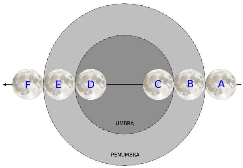
Due to the fact that the Sun is not a point source, the shadow of the Earth on the Moon has an area of complete shadow, called the umbra, surrounded by an area of partial shadow called the penumbra, as shown below.

The diameter of the Earth's shadow (the umbra) at the Moon is 9200 km .

figure
A\begin{tabular}{l} Moon enters
Penumbra

& 2:37 a.m.
\hline B &

Partial eclipse
begins

& 3:34 a.m.
\hline C &

Total eclipse
begins

& 4:41 a.m.
\hline D &

Total eclipse
ends

& 5:43 a.m.
\hline E &

Partial eclipse
ends

& 6:50 a.m.
\hline F &

Moon leaves
Penumbra

& 7:48 a.m.
\hline \endtabular

(Lunar image: free for commercial use, no attribution required)

\footnotetext* Note: Umbra, penumbra and size of the Moon are NOT SHOWN TO SCALE in the diagram * A partial lunar eclipse occurs when part of the Moon is in the shadow of the Earth (the umbra).

A total lunar eclipse occurs when the Moon is entirely within the umbra of the Earth's shadow. Assume, in the following questions, that the Moon passed through the widest part of the Earth's shadow during the total lunar eclipse.*
(b) By considering the time interval between appropriate points in the lunar eclipse, show that the speed of the Moon* in its orbit as seen from Earth is calculated as approximately $4300 \mathrm{~km} / \mathrm{h}$.
(c) By considering the time between the appropriate points in the lunar eclipse and the speed calculated previously, show that the diameter of the Moon* is approximately 4800 km .
(d) Given that the period of the Moon's orbit is 27.3 days, calculate the distance between the Earth and the Moon.

  • The lunar eclipse that occurred on $21^{\text {st }}$ January passed completely through the umbra but crossed at an angle just to the North of the ecliptic, meaning that it did not quite pass through the widest part. In addition the motion of the Earth is not taken into account. The values for the speed and size of the Moon and Earth - Moon distance calculated in the question are, as a result, significantly higher than the accepted values.
    The sidereal period, the time taken to complete a $360^{\circ}$ path around the Earth relative to the fixed background stars, is approximately 27.3 days. Due to the Earth's own motion in its orbit, the synodic period, the time between successive full moons, is longer at approximately 29.5 days
    (e) It is claimed that a thumb, held at arm's length, will almost exactly obscure the full moon.

By estimating the size of your thumb and the distance between your eye and your thumb at arm's length, discuss the validity of this claim.
[0pt]

Show worked solution
(a)

A suitable labelled diagram should show the Sun, Earth, and Moon in a straight line with the Earth between the Sun and the Moon (this must occur at full moon), and the Moon lying inside the Earth’s shadow (umbra) for a total eclipse. One possible sketch is below (not to scale): $$ \begin{tikzpicture}[scale=0.95] \draw (-6,0) circle (0.55) node[left=10pt]{Sun}; \draw (0,0) circle (0.45) node[below=8pt]{Earth}; \draw (6,0) circle (0.25) node[right=10pt]{Moon}; \draw[thick] (-0.1,0.28) -- (7.2,0.75); \draw[thick] (-0.1,-0.28) -- (7.2,-0.75); \draw[dashed] (-0.1,0.45) -- (7.2,1.30); \draw[dashed] (-0.1,-0.45) -- (7.2,-1.30); \node at (4.2,0.05) {umbra}; \node at (4.2,1.0) {penumbra}; \node at (4.2,-1.0) {penumbra}; \end{tikzpicture} $$ A total lunar eclipse is not observed every lunar month because the Moon’s orbital plane is tilted by about $5^\circ$ to the Earth’s orbital plane (the ecliptic). Most full moons occur when the Moon is slightly above or below the Earth–Sun line, so it misses the Earth’s umbra. A lunar eclipse only occurs when a full moon happens close to a node, where the Moon’s orbit crosses the ecliptic, allowing alignment with the Earth’s shadow.

(b)

The Moon’s orbital speed as seen from Earth can be found by using the time spent in the umbra. From the table, the partial eclipse (umbra contact) lasts from $B$ to $E$, and totality lasts from $C$ to $D$. The durations are $t_{BE}=3\ \mathrm{h}\ 16\ \mathrm{min}=3.267\ \mathrm{h}$ and $t_{CD}=1\ \mathrm{h}\ 02\ \mathrm{min}=1.033\ \mathrm{h}$. During $B\to E$ the Moon’s disc moves across the umbra from first contact to last contact, so the travelled distance equals $D_u+D_m$ where $D_u=9200\ \mathrm{km}$ is the umbra diameter at the Moon and $D_m$ is the Moon diameter. During $C\to D$ the Moon moves from “just fully inside” to “just about to leave fully inside”, so the travelled distance equals $D_u-D_m$. Adding these two distances eliminates $D_m$: $$ v(t_{BE}+t_{CD})=(D_u+D_m)+(D_u-D_m)=2D_u $$ $$ v=\frac{2D_u}{t_{BE}+t_{CD}}=\frac{2(9200)}{3.267+1.033}\approx \frac{18400}{4.300}\approx 4.28\times 10^3\ \mathrm{km\,h^{-1}}\approx 4300\ \mathrm{km\,h^{-1}} $$ So the Moon’s orbital speed as seen from Earth is approximately $4300\ \mathrm{km\,h^{-1}}$.

(c)

Using the same geometry, subtracting the two travelled distances isolates the Moon’s diameter. $$ v(t_{BE}-t_{CD})=(D_u+D_m)-(D_u-D_m)=2D_m $$ $$ D_m=\frac{v(t_{BE}-t_{CD})}{2}=\frac{(4300)(3.267-1.033)}{2}=\frac{(4300)(2.234)}{2}\approx 4.80\times 10^3\ \mathrm{km}\approx 4800\ \mathrm{km} $$ Hence the Moon’s diameter is approximately $4800\ \mathrm{km}$.

(d)

Treating the Moon’s orbit as approximately circular, the orbital circumference is $2\pi r$ and the speed is $v=2\pi r/T$, so $r=vT/(2\pi)$. The period is $T=27.3\ \mathrm{days}=27.3\times 24=655.2\ \mathrm{h}$. $$ r=\frac{vT}{2\pi}=\frac{(4300)(655.2)}{2\pi}\ \mathrm{km}\approx \frac{2.82\times 10^6}{6.283}\ \mathrm{km}\approx 4.48\times 10^5\ \mathrm{km} $$ So the Earth–Moon distance is approximately $4.5\times 10^5\ \mathrm{km}$.

(e)

The claim depends on angular size. For a thumb of width $w$ held a distance $L$ from the eye, the angular size (in radians) is approximately $\theta \approx w/L$. Taking a typical arm’s length $L\approx 0.60\ \mathrm{m}$ and a typical thumb width $w\approx 0.020\ \mathrm{m}$ gives $\theta \approx 0.020/0.60 \approx 0.033\ \mathrm{rad}\approx 1.9^\circ$. The full Moon’s angular diameter is about $0.5^\circ$ (roughly $0.009\ \mathrm{rad}$), so a typical thumb at arm’s length subtends several times the Moon’s diameter and will certainly obscure it, but not “almost exactly”. For the thumb to match the Moon’s angular size at $L=0.60\ \mathrm{m}$, the required width would be $w\approx L\theta \approx 0.60\times 0.009 \approx 0.005\ \mathrm{m}\approx 0.5\ \mathrm{cm}$, which is much smaller than most people’s thumb widths, so the claim is only weakly valid (it will cover the Moon, but usually with a significant margin).

2019-14C · Writtend3Mechanics and Energy · Gas laws and absolute zero

(2019-14) Glass food jars have a 'safety seal' to guarantee that the jar has not been opened since manufacture. The metal lid has a depression which "pops" or "clicks" when the jar is opened.

The safety seal works by having a lower pressure inside the jar. The greater atmospheric pressure keeps the metal lid depressed. When the jar is opened the pressure inside the jar increases and the lid snaps back into its original shape making the characteristic popping sound.

Assume atmospheric pressure is 101 kPa

The centre part of the lid is depressed (pulled in to the jar) when it is sealed and pops back out when the jar is first opened

figure

(a) The force required to "pop" or depress a jam jar lid with a centre part diameter of 4.0 cm is found to be 13 N .

Show that the pressure required to depress the lid is about 10 kPa
(b) An empty jam jar is gently heated in an oven to a temperature of $80^{\circ} \mathrm{C}$. The lid is put on tightly to make an air tight seal and the jam jar allowed to cool from $80^{\circ} \mathrm{C}$. The safety seal "pops" down and is fully depressed when the jam jar reaches a temperature of $38^{\circ} \mathrm{C}$.

Using the result from part (a), calculate the pressure inside the jam jar at $38^{\circ} \mathrm{C}$.
[0pt] [2 marks]
(c) The pressure of a gas becomes zero when the temperature falls to absolute zero. Use the results of the experiment with the jam jar to estimate a value for the absolute zero of temperature.
[0pt] [4 marks]
(d) State one assumption necessary to be able use the results of the experiment to calculate the value of absolute zero.
(e) The experiment is repeated but this time the jam jar is half full of jam. Explain whether or not this change affects the temperature at which the safety seal pops down.
(f) The accepted value for absolute zero is $-273^{\circ} \mathrm{C}$. Therefore, one or more of the values determined experimentally must have been incorrect.

By thinking about how the measurements might have been made, suggest which of the measurements in the experiment is most likely to have caused the difference between the value calculated in part (c) and the accepted value. Explain whether the measurement suggested was too low or too high.

Show worked solution
(a)

The popping happens because there is a pressure difference across the depressed centre of the lid, so the net force is $F=\Delta P\,A$, where $A$ is the area of the depressed circular part. The diameter is $4.0\ \mathrm{cm}$ so the radius is $r=2.0\ \mathrm{cm}=2.0\times 10^{-2}\ \mathrm{m}$. $$ A=\pi r^2=\pi(2.0\times 10^{-2})^2=1.26\times 10^{-3}\ \mathrm{m^2} $$ $$ \Delta P=\frac{F}{A}=\frac{13}{1.26\times 10^{-3}}=1.0\times 10^{4}\ \mathrm{Pa}\approx 10\ \mathrm{kPa} $$ So the pressure difference needed to depress the lid is about $10\ \mathrm{kPa}$, as required.

(b)

When the seal pops down, the outside atmospheric pressure exceeds the inside pressure by about $10\ \mathrm{kPa}$. With $P_{\mathrm{atm}}=101\ \mathrm{kPa}$, the pressure inside at $38^\circ\mathrm{C}$ is $$ P_{\mathrm{in}}=P_{\mathrm{atm}}-\Delta P=101\ \mathrm{kPa}-10\ \mathrm{kPa}=91\ \mathrm{kPa} $$ So $P_{\mathrm{in}}\approx 91\ \mathrm{kPa}$ at $38^\circ\mathrm{C}$.

(c)

For a fixed amount of gas in a sealed jar of fixed volume, the pressure is proportional to absolute temperature $T$, so pressure varies linearly with Celsius temperature $\theta$ and would reach zero at absolute zero $\theta_0$. Using the two experimental points $(\theta_1,P_1)=(80^\circ\mathrm{C},101\ \mathrm{kPa})$ and $(\theta_2,P_2)=(38^\circ\mathrm{C},91\ \mathrm{kPa})$, the slope is $$ m=\frac{P_1-P_2}{\theta_1-\theta_2}=\frac{101-91}{80-38}=\frac{10}{42}=0.238\ \mathrm{kPa\,^\circ C^{-1}} $$ Using $P=m(\theta-\theta_0)$ and substituting $(\theta_1,P_1)$ gives $$ 101=m(80-\theta_0)\ \Rightarrow\ \theta_0=80-\frac{101}{m}=80-\frac{101}{0.238}\approx -3.44\times 10^2\ ^\circ\mathrm{C} $$ So the experiment estimates absolute zero as approximately $-344^\circ\mathrm{C}$.

(d)

An assumption needed is that the amount of gas in the jar remains constant (no leaks in or out after the lid is tightened).

(e)

If the jar is half full of jam, the volume of trapped air is smaller, but for a sealed jar the pressure change with temperature still follows $P\propto T$ and does not depend on the volume, because $P/T=nR/V$ and both $n$ and $V$ are constant after sealing. Therefore, in the idealised model the temperature at which the seal pops down is unchanged. In practice, the jam can release water vapour and change $n$, which would change the pressure and could shift the popping temperature.

(f)

The largest likely cause is an error in the temperature of the gas when the lid was sealed at “$80^\circ\mathrm{C}$”. The jar (and especially the air inside it) may not actually have been at $80^\circ\mathrm{C}$ when the lid was tightened, because the oven setting or a thermometer reading does not guarantee the trapped air had reached that temperature. If the true sealing temperature was lower than $80^\circ\mathrm{C}$ but was recorded as $80^\circ\mathrm{C}$, then $\theta_1-\theta_2$ was taken too large, making the slope $m=\Delta P/\Delta\theta$ too small and causing the extrapolated intercept $\theta_0=80-101/m$ to be too negative. This would help explain why the calculated absolute zero (about $-344^\circ\mathrm{C}$) is more negative than the accepted $-273^\circ\mathrm{C}$.

2020-12B · Writtend2Mechanics and Energy · Ammeter design — low resistance in series

(2020-12) In a simple circuit the ammeter is connected in series and the voltmeter is connected in parallel.

figure

Explain why an ammeter should have a (very) low resistance.

Show worked solution
Key idea

An ammeter is designed to measure the current through a component, so it must be placed in series with that component. In a series connection, the same current flows through every element, meaning the ammeter becomes part of the path that the current must take.

Why the resistance must be very low

If the ammeter had a significant resistance, it would add extra resistance to the circuit. Since the total series resistance would increase, the current in the circuit would decrease, so the act of measuring the current would change the current being measured. Using Ohm's law, the current in a simple series circuit is

$$ I=\frac{V}{R_{\text{load}}+R_A} $$

where $R_{\text{load}}$ is the resistance of the rest of the circuit and $R_A$ is the ammeter resistance. To ensure the measured current is as close as possible to the current that would flow without the ammeter, we need $R_A \ll R_{\text{load}}$, so that adding the ammeter does not noticeably change the denominator.

Minimising energy loss and voltage drop across the ammeter

A non-negligible ammeter resistance would cause a voltage drop across the ammeter, reducing the potential difference available to the component being tested. The voltage drop across the ammeter is

$$ V_A=IR_A $$

For an ideal ammeter, we want $V_A \approx 0$, which requires $R_A$ to be very small. Also, any resistance in the ammeter would dissipate power as heat,

$$ P_A=I^2R_A $$

so a very low $R_A$ minimises heating and wasted energy, improving both safety and measurement accuracy.

Conclusion

An ammeter should have a (very) low resistance so that, when connected in series, it causes negligible change to the circuit current, produces negligible voltage drop, and dissipates negligible power, allowing it to measure current without significantly disturbing the circuit.

2020-14C · Writtend4Mechanics and Energy · Schwarzschild radius and angular resolution

(2020-14) In April 2019 The Event Horizon Telescope (EHT) collaboration published the first direct image (shown below) of a supermassive black hole named M87* (read as M87 star) at the centre of a nearby galaxy named M87.

A black hole is a massive astronomical object so dense that even light cannot escape its enormous gravitational field.

The radius of the event horizon of a black hole is the distance from the centre at which light cannot escape and can be thought of as the "size" of the black hole.

The photograph published by the Event Horizon Telescope collaboration shows a dark region of shadow about $\mathbf{2 . 5}$ times the diameter of the event horizon surrounded by clouds of brightly glowing gas.

The following information is required:

  • Mass of the Sun $=2 \times 10^{30} \mathrm{~kg}$
  • Distance from Sun to Earth $=1 \mathrm{AU}$
  • Distance from Sun to Pluto $=40 \mathrm{AU}$
  • $1 \mathrm{AU}=1.5 \times 10^{11} \mathrm{~m}$
  • Radius of Earth $=6400 \mathrm{~km}$
  • Mass of M87* $=6.5 \times 10^{9}$ solar masses
  • Distance to M87* $=55$ million light years
  • Gravitational constant, $\mathrm{G}=6.67 \times 10^{-11} \mathrm{~N} \mathrm{~m}^{2} / \mathrm{kg}^{2}$
  • Speed of light, $c=3 \times 10^{8} \mathrm{~m} / \mathrm{s}$

Notes: AU is a measurement of distance called an Astronomical Unit.
A light year is a measurement of distance equal to the distance travelled by light in one (Earth) year.
(a) Before direct imaging was possible, suggest how astronomers could have identified the location of black holes.
[0pt] [1 mark]
(b) After the release of the image of M87*, one news article claimed "The black hole M87* is as big as our entire Solar System"

The radius of the event horizon of a black hole is given by the equation for the Schwarzschild radius $\left(r_{S}\right)^{\dagger}$,

$$ r_{S}=\frac{2 G M}{c^{2}} \quad \text { where } M \text { is the mass of the black hole } $$

Use the information given to compare the radius of the event horizon of M87* and the radius of the solar system and hence comment on the validity of the claim.
[0pt] [4 marks]
(c) (i) Show that the distance to M87* is about $5 \times 10^{23} \mathrm{~m}$
(c) (ii) Astronomers observing a far away object calculate the angular size of an object.

The angular size is the angle ( $\phi$ ) from one edge of the object to the other as observed from Earth.

figure

Using the photograph, show that the angular size of the image of M87* (including the glowing gas clouds) is about $30 \times 10^{-9}$ degrees
(c) (iii) The angular resolution of a telescope is the smallest angle (R) between two objects such that they can been seen as separate.

The angular resolution $(R)$ is given by $R \approx 60 \times \lambda$ / $D$ where $\lambda$ is the wavelength of the radiation being detected, $D$ is the diameter of the telescope aperture and $R$ is measured in degrees. $D$ and $\lambda$ are in the same units.

The Event Horizon Telescope uses a consortium of smaller telescopes from across the globe all connected together so that the effective diameter of the EHT is approximately the diameter of the earth.
Given that the EHT observes radiation at a frequency of $230 \mathrm{GHz}\left(1 \mathrm{GHz}=1 \times 10^{9} \mathrm{~Hz}\right)$, show that the EHT has a good enough resolution to produce the image of M87*.

Show worked solution
(a)

Astronomers could identify black hole locations indirectly by observing the motion of nearby stars and gas: if stars orbit a point in space where there is little or no visible matter, the orbits (via Newtonian/relativistic gravity) imply a very large unseen mass concentrated in a very small region; additionally, intense radiation from hot accreting gas and relativistic jets can indicate matter falling toward a compact object even though the black hole itself emits no light.

(b)

The mass of M87* is $M=6.5\times 10^{9}$ solar masses, so using $M_\odot=2\times10^{30}\,kg$ gives $M=6.5\times10^{9}\times2\times10^{30}=1.3\times10^{40}\,kg$. The Schwarzschild radius is $$ r_S=\frac{2GM}{c^2}=\frac{2(6.67\times10^{-11})(1.3\times10^{40})}{(3\times10^8)^2}\approx\frac{1.734\times10^{30}}{9\times10^{16}}\approx1.9\times10^{13}\,m $$ Converting to astronomical units using $1\,AU=1.5\times10^{11}\,m$, $$ r_S\approx \frac{1.9\times10^{13}}{1.5\times10^{11}}\approx1.3\times10^{2}\,AU\approx130\,AU $$ A simple “radius of the solar system” estimate using Pluto’s orbit is $40\,AU$, so $r_S/r_{solar}\approx130/40\approx3.3$, meaning the event horizon radius of M87* is a few times larger than the Sun--Pluto distance. In terms of diameters, the event horizon diameter is $2r_S\approx260\,AU$, whereas the Sun--Pluto diameter is $2\times40=80\,AU$, so the event horizon diameter is also several times larger than the “Pluto-sized” solar system. Since the image shadow is about $2.5$ times the event horizon diameter, its diameter would be even larger, about $2.5\times260\,AU\approx650\,AU$. Therefore the claim “as big as our entire Solar System” is qualitatively in the right direction (it is on solar-system scales), but quantitatively it is an underestimate if the solar system is taken to mean out to Pluto.

(c)(i)

One light year is the distance light travels in one year, so with $c=3\times10^8\,m\,s^{-1}$ and $1\,year\approx365\times24\times3600\approx3.15\times10^{7}\,s$, $$ 1\,ly\approx (3\times10^8)(3.15\times10^{7})\approx9.45\times10^{15}\,m $$ The distance is $55$ million light years $=55\times10^{6}\,ly$, hence $$ d\approx(55\times10^{6})(9.45\times10^{15})\approx5.2\times10^{23}\,m\approx5\times10^{23}\,m $$

(c)(ii)

From the photograph, the full bright image (including the glowing gas clouds) is about $2.7$ times the diameter of the dark shadow. The dark shadow diameter is about $2.5$ times the event horizon diameter, so the bright image diameter is approximately $$ D_{img}\approx(2.7)(2.5)(2r_S)=13.5\,r_S\approx 13.5(1.9\times10^{13})\approx2.6\times10^{14}\,m $$ Using the small-angle approximation $\phi\simeq D_{img}/d$ (in radians) with $d\approx5\times10^{23}\,m$, $$ \phi \approx \frac{2.6\times10^{14}}{5\times10^{23}} \approx 5.2\times10^{-10}\,rad $$ Converting radians to degrees using $1\,rad=180/\pi$ degrees, $$ \phi \approx (5.2\times10^{-10})\frac{180}{\pi}\approx (5.2\times10^{-10})(57.3)\approx3.0\times10^{-8}\,degrees=30\times10^{-9}\,degrees $$ which matches the required angular size.

(c)(iii)

The observing frequency is $f=230\,GHz=230\times10^9\,Hz$, so the wavelength is $$ \lambda=\frac{c}{f}=\frac{3\times10^8}{230\times10^9}\approx1.3\times10^{-3}\,m $$ The effective aperture diameter is approximately Earth’s diameter, $D\approx2(6400\,km)=12800\,km=1.28\times10^{7}\,m$. The angular resolution in degrees is $$ R\approx 60\frac{\lambda}{D}\approx 60\frac{1.3\times10^{-3}}{1.28\times10^{7}}\approx6.1\times10^{-9}\,degrees $$ Since $R\approx6\times10^{-9}\,degrees$ is smaller than the angular size of the image $\phi\approx30\times10^{-9}\,degrees$, the EHT has sufficiently fine angular resolution to resolve M87* and produce the observed image.

2022-11B · Writtend2Mechanics and Energy · Eclipse geometry and shadow formation

(2022-11) In 2022 there will be two solar eclipses and two lunar eclipses.
The partial solar eclipse on $30^{\text {th }}$ April will only be visible in the south of South America and Antarctica. The total lunar eclipse on $15^{\text {th }}$ May will be visible across most of North America, all of South America, much of southern Europe, south west Asia, all of Africa and Antarctica.

Explain why a solar eclipse can be observed directly from only a relatively small area of Earth whereas a lunar eclipse can be observed directly from many different places on Earth covering a much larger area.

You should draw a diagram.

Show worked solution
Explanation with diagram
A solar eclipse and a lunar eclipse both happen because the Sun, Earth and Moon line up closely, but the size of the shadow and where it falls are very different. The key difference is where the shadow is formed and how large the shadow is when it reaches the object being eclipsed.

\begintikzpicture[scale=0.95] % Objects \draw[fill=yellow!60,draw=orange!80] (-6,0) circle (0.7) node[below=8pt] Sun; \draw[fill=gray!40] (-1.5,0) circle (0.25) node[below=8pt] Moon; \draw[fill=blue!30,draw=blue!60] (3,0) circle (0.55) node[below=8pt] Earth; \draw[fill=gray!30] (6.2,0) circle (0.25) node[below=8pt] Moon;

% Rays for solar eclipse (Moon shadow on Earth) \draw (-5.3,0.55) -- (-1.5,0.25); \draw (-5.3,-0.55) -- (-1.5,-0.25); \draw (-1.5,0.25) -- (2.6,0.10); \draw (-1.5,-0.25) -- (2.6,-0.10); \draw[thick] (2.6,0.10) -- (2.6,-0.10); \node at (1.0,0.35) umbra/penumbra; \node at (2.75,0.0) small shadow;

% Rays for lunar eclipse (Earth shadow on Moon) \draw (-5.3,0.55) -- (3,0.55); \draw (-5.3,-0.55) -- (3,-0.55); \draw (3,0.55) -- (6.2,0.25); \draw (3,-0.55) -- (6.2,-0.25); \draw[thick] (6.0,0.25) -- (6.0,-0.25); \node at (4.6,0.75) Earth shadow; \node at (6.35,0.0) Moon enters shadow;

% Observers \fill (3.45,0.35) circle (0.04) node[right] observer in eclipse path; \fill (2.55,0.45) circle (0.04); \fill (2.55,-0.45) circle (0.04); \node at (1.7,-1.05) Solar eclipse visible only where Moon's shadow hits Earth; \node at (5.2,-1.05) Lunar eclipse visible from most of Earth's night side; \endtikzpicture

Why a solar eclipse is visible from a small area
During a solar eclipse the Moon blocks the Sun, so the Moon’s shadow must fall on Earth. The Moon is much smaller than Earth, so its shadow cone is narrow. Only the region of Earth that lies inside the Moon’s umbra sees a total solar eclipse; regions in the penumbra see only a partial solar eclipse. Because the umbra is typically only of order $10^2\ \mathrm{km}$ wide when it reaches Earth, the “path of totality” is a thin strip across Earth’s surface. Also, because the Moon and Earth move, this narrow shadow sweeps across the surface, so any given location is in the eclipse for only a short time.
Why a lunar eclipse is visible from a large area
During a lunar eclipse, Earth blocks sunlight from reaching the Moon, so Earth’s shadow falls on the Moon. Earth is much larger than the Moon, so its shadow at the Moon’s distance is much wider than the Moon itself. Any observer on the night side of Earth who can see the Moon above their horizon can watch the Moon darken, so the eclipse is visible from a very large fraction of Earth (roughly the entire hemisphere for which it is nighttime and the Moon is up). This is why a lunar eclipse can be seen across continents, whereas a solar eclipse is restricted to the comparatively tiny region where the Moon’s shadow reaches Earth.
Helpful size comparison (conceptual)
The Sun and Moon have nearly the same angular size as seen from Earth, which is why the Moon can cover the Sun, but the shadow on Earth is still narrow because the Moon is small. Earth’s shadow at the Moon is large because Earth’s diameter is large compared with the Moon’s, so many places on Earth can simultaneously observe the Moon passing through that shadow.
2022-14C · Writtend5Mechanics and Energy · Photon energy and laser pulse power

(2022-14) This question is about some of the challenges that need to be overcome when determining the distance to the Moon by measuring the round-trip-time of a laser beam reflected from the surface (Lunar Laser Ranging).

In 1969, Apollo 11 astronauts placed a mirror on the Moon. The mirror, called a retroreflector, is made from a number of "corner cubes" which act like prisms to reflect light due to total internal reflection.

figure

a) Complete the path of the incident light ray on the diagram to show the reflected light ray emerging from the prism.

figure

b) Explain why a prism arrangement, relying on total internal reflection, is a better choice of reflector on the Moon's surface than a simple plane mirror (like you might find in a bathroom).
The laser beam can be thought of as a stream of "particles of light" called photons.
Each photon of light has an energy $(E)$ that depends on the frequency $(f)$ of the light and a constant called the Planck constant ( $h$ ).

The equation for the energy (E) of a single photon is: $E=h \times f$ where $h$ denotes the Planck constant and has a value of $h=6.63 \times 10^{-34} \mathrm{Js}$

One particular Lunar Laser Ranging experiment uses short pulses of green laser light with a wavelength of $532 \mathrm{~nm}\left(532 \times 10^{-9} \mathrm{~m}\right)$.

The duration of each pulse is $100 \mathrm{ps}\left(100 \times 10^{-12} \mathrm{~s}\right)$. The energy in each pulse is 115 mJ .
c) Show that the power of the laser is approximately 1 GW
d) Show that the frequency of the laser light is approximately $5.6 \times 10^{14} \mathrm{~Hz}$
e) Hence calculate the number of photons of light in a single pulse of laser light
f) Explain why pulses of laser light are used rather than a continuous beam of laser light
As the pulse of laser light travels towards the Moon, the beam spreads out (or diverges).
The divergence of the laser beam is approximately $1.00 \times 10^{-3}$ degrees and the distance between the Earth and the Moon is approximately 384000 km . See diagram (not to scale).

figure

g) Show that when the laser beam reaches the Moon, it covers an area approximately 7 km in diameter. Assume that the laser beam forms a circular pattern.
The reflector placed on the Moon is a square with each side measuring 46 cm .
h) Show that the number of photons incident on the reflector from each pulse of laser light is approximately $2 \times 10^{9}$ photons.
Assume that the entire surface reflects incoming photons of light. The telescope used to detect the returning photons has a diameter of 3.50 m
i) Hence show that the (theoretical) number of photons received by the telescope from each pulse of laser light is only about 500 .
Modern Lunar Laser Ranging experiments use very precise timing to determine the distance to the Moon to within 15 mm (or better).

The atmosphere can be modelled as a layer of air 12 km in depth with a constant refractive index of 1.0003 .
j) Determine whether or not the effect of the atmosphere on the speed of light needs to be taken into consideration when conducting Lunar Laser Ranging experiments to this level of precision.
The results of Lunar Laser Ranging experiments show that the distance between the Earth and the Moon is increasing by about 3.8 cm per year.
k) What difference, if any, would we have noticed if we looked up at the full Moon in the night sky towards the end of the Stone Age, 10000 years ago?

Show worked solution
(a)

A corner-cube retroreflector has three mutually perpendicular reflecting faces. The incident ray enters the prism, then undergoes total internal reflection from each of the three internal faces in turn, and finally emerges back out of the prism travelling antiparallel to the incident ray (same line but opposite direction, usually with a small sideways displacement). On the diagram, the completed path should show three reflections inside the prism and an emerging ray pointing back towards the source.

(b)

A plane mirror only reflects light back to the source if it is aligned extremely accurately: if the mirror is tilted by a small angle, the reflected beam direction changes by twice that angle, so the returning beam will usually miss the Earth-based telescope. A corner-cube prism arrangement is a retroreflector: after three reflections it returns light back in (almost) exactly the opposite direction to the incoming beam regardless of how the reflector is oriented, so it still works even if the Moon-based reflector is not perfectly aligned. Also, because it relies on total internal reflection rather than a metallic coating, the reflecting surfaces are protected within the prism and do not rely on an exposed reflective layer that could degrade.

(c)

The (peak) power during a pulse is the pulse energy divided by the pulse duration: $$ P=\frac{E_{\text{pulse}}}{\Delta t}=\frac{115\times 10^{-3}\,J}{100\times 10^{-12}\,s}=1.15\times 10^{9}\,W\approx 1\,GW $$

(d)

The frequency is related to wavelength by $c=f\lambda$, so $$ f=\frac{c}{\lambda}=\frac{3.00\times 10^{8}\,m\,s^{-1}}{532\times 10^{-9}\,m}=5.64\times 10^{14}\,Hz\approx 5.6\times 10^{14}\,Hz $$

(e)

Energy per photon is $E_\gamma=hf$, so using $h=6.63\times 10^{-34}\,Js$ and $f\approx 5.6\times 10^{14}\,Hz$: $$ E_\gamma=hf=(6.63\times 10^{-34})(5.6\times 10^{14})\approx 3.7\times 10^{-19}\,J $$ The number of photons in one pulse is $N=E_{\text{pulse}}/E_\gamma$: $$ N=\frac{0.115\,J}{3.7\times 10^{-19}\,J}\approx 3.1\times 10^{17}\ \text{photons} $$

(f)

Pulses are used because the distance is found from the round-trip time-of-flight: a short pulse gives a well-defined emission time and a well-defined return time, so the time delay (and hence distance) can be measured very precisely. Pulses also allow “time-gating” of the detector so it mainly looks only when the return is expected, greatly reducing background light, and they provide extremely high peak power (helping detect a tiny return signal) while keeping the average power and heating manageable.

(g)

Convert the divergence to radians: $$ \theta=1.00\times 10^{-3}\,^{\circ}\times \frac{\pi}{180}\approx 1.75\times 10^{-5}\,rad $$ For small angles, the beam diameter at distance $L$ is approximately $D\approx L\theta$. With $L=384000\,km=3.84\times 10^{8}\,m$: $$ D\approx (3.84\times 10^{8})(1.75\times 10^{-5})\approx 6.7\times 10^{3}\,m\approx 7\,km $$ So the beam covers a circular spot about $7\,km$ in diameter on the Moon.

(h)

The area of the beam spot on the Moon (diameter $\approx 7\,km$, radius $r=3.5\,km=3500\,m$) is $$ A_{\text{spot}}=\pi r^{2}=\pi(3500)^{2}\approx 3.85\times 10^{7}\,m^{2} $$ The reflector is a square of side $0.46\,m$, so $$ A_{\text{refl}}=(0.46)^{2}=0.2116\,m^{2} $$ Assuming photons are spread uniformly across the spot, the fraction that hits the reflector is $A_{\text{refl}}/A_{\text{spot}}$, so the number incident on the reflector is $$ N_{\text{refl}}=N\frac{A_{\text{refl}}}{A_{\text{spot}}}\approx (3.1\times 10^{17})\frac{0.2116}{3.85\times 10^{7}}\approx 1.7\times 10^{9}\approx 2\times 10^{9}\ \text{photons} $$

(i)

Assume those photons are reflected and spread over the same beam area when they return to Earth, $A_{\text{spot}}\approx 3.85\times 10^{7}\,m^{2}$. The telescope (diameter $3.50\,m$, radius $1.75\,m$) has collecting area $$ A_{\text{tel}}=\pi(1.75)^{2}\approx 9.62\,m^{2} $$ The fraction captured is $A_{\text{tel}}/A_{\text{spot}}$, so the received photon number is $$ N_{\text{rec}}=N_{\text{refl}}\frac{A_{\text{tel}}}{A_{\text{spot}}}\approx (2\times 10^{9})\frac{9.62}{3.85\times 10^{7}}\approx 5.0\times 10^{2} $$ So the theoretical number received is about $500$ photons per pulse.

(j)

Light travels slower in air: $v=c/n$. If the atmosphere is thickness $12\,km$ each way, the total air path for the round trip is $L_{\text{air}}=24\,km=2.4\times 10^{4}\,m$. The extra time compared with vacuum is $$ \Delta t=\frac{nL_{\text{air}}}{c}-\frac{L_{\text{air}}}{c}=\frac{(n-1)L_{\text{air}}}{c}=\frac{(0.0003)(2.4\times 10^{4})}{3.0\times 10^{8}}\approx 2.4\times 10^{-8}\,s $$ If this were ignored, the inferred distance error would be half of $c\Delta t$ (because the timing is round-trip): $$ \Delta d=\frac{c\Delta t}{2}=\frac{(n-1)L_{\text{air}}}{2}=\frac{0.0003\times 2.4\times 10^{4}}{2}\approx 3.6\,m $$ Since $3.6\,m \gg 15\,mm$, the atmospheric effect must be taken into account for millimetre-level ranging.

(k)

Over $10000$ years, the increase in Earth–Moon distance is $$ \Delta r=(3.8\,cm\,yr^{-1})(10000\,yr)=3.8\times 10^{4}\,cm=380\,m $$ Compared with $r\approx 3.84\times 10^{8}\,m$, the fractional change is $\Delta r/r\approx 1.0\times 10^{-6}$. The Moon’s angular diameter is inversely proportional to distance, so its fractional change in apparent size would also be about $10^{-6}$, far below what the human eye can detect. We would notice no visible difference in the full Moon’s size in the sky.

2023-13C · Writtend4Mechanics and Energy · Gravitational potential energy storage

(2023-13: Gravity Batteries) This question is about the possibility of large-scale energy storage in the form of gravitational potential energy of large masses. Several such systems are currently being developed and are often referred to as gravity batteries. These energy storage systems are designed to contribute energy to the national grid at short notice when demand is high.

One such system uses large masses lowered down disused mine shafts or purpose built shafts. At times of low demand, when excess electrical energy is available, electric winches raise the masses. At times of high demand, when extra energy is required by the national grid, the masses are allowed to descend with the winch systems acting as electrical generators.

Domestic electrical energy is measured in units of kilowatt-hours (kWh) where 1 kWh is the energy transferred at a rate of 1 kW for 1 hour.
a) Show that 1 kWh is equivalent to $3.6 \times 10^{6} \mathrm{~J}$

The gravity battery system uses a container of crushed rock as the large mass. The container is cylindrical with a diameter of 5.0 m and a depth of 4.0 m. It is filled with crushed rock with an average density of $5200 \mathrm{~kg} / \mathrm{m}^{3}$.

The mass can be raised or lowered a total distance of 300 m in the shaft.
b) Calculate the maximum energy that can be stored by the gravity battery in units of kWh.

At one particular instant, the gravity battery is required to provide energy to the national grid at a rate of 800 kW.

The electrical generators operate with an efficiency of $94 \%$.
c) Calculate the speed at which the mass descends.

d) Hence, or otherwise, calculate how long the gravity battery can provide energy to the national grid at a rate of 800 kW.

Eight cables are used to support the mass. Cables have the following properties:

  • Maximum tensile force 2100 kN
  • Density $7850 \mathrm{~kg} / \mathrm{m}^{3}$
  • Diameter 8.7 cm
  • Safe working load $\frac{1}{3} \times$ maximum tensile force
  • Number of cables: 8

The acceleration of the mass must be carefully controlled to avoid breaking the support cables.
e) Ignoring the weight of the cables, show that the maximum acceleration of the mass must be just less than $4 \mathrm{~m} / \mathrm{s}^{2}$.

In reality the weight of the cables themselves is significant and cannot be ignored, especially when they are fully extended.
f) Show that, if the maximum acceleration of the mass is assumed to be very small, the cables are suitable for supporting the mass at a depth of 300 m.

Show worked solution
(a)

A kilowatt-hour is the energy transferred by a power of $1\,\mathrm{kW}=1000\,\mathrm{W}$ acting for $1\,\mathrm{h}=3600\,\mathrm{s}$. Using $E=Pt$, $$ E=(1000\,\mathrm{W})(3600\,\mathrm{s})=3.6\times 10^{6}\,\mathrm{J} $$ So $1\,\mathrm{kWh}=3.6\times 10^{6}\,\mathrm{J}$.

(b)

The container is a cylinder of radius $r=2.5\,\mathrm{m}$ and depth $h=4.0\,\mathrm{m}$, so its volume is $$ V=\pi r^{2}h=\pi(2.5)^{2}(4.0)=25\pi\approx 78.5\,\mathrm{m^{3}} $$ With crushed rock density $\rho=5200\,\mathrm{kg\,m^{-3}}$, the mass is $$ m=\rho V=5200\times 78.5\approx 4.08\times 10^{5}\,\mathrm{kg} $$ The maximum gravitational potential energy stored by raising it by $\Delta y=300\,\mathrm{m}$ is $$ E_{\max}=mg\Delta y=(4.08\times 10^{5})(9.81)(300)\approx 1.20\times 10^{9}\,\mathrm{J} $$ Convert to kWh using $1\,\mathrm{kWh}=3.6\times 10^{6}\,\mathrm{J}$: $$ E_{\max}\approx \frac{1.20\times 10^{9}}{3.6\times 10^{6}}\approx 3.34\times 10^{2}\,\mathrm{kWh}\approx 334\,\mathrm{kWh} $$

(c)

The grid requires electrical power $P_{\mathrm{e}}=800\,\mathrm{kW}$. With generator efficiency $\eta=0.94$, $$ \eta=\frac{P_{\mathrm{e}}}{P_{\mathrm{mech}}}\quad\Rightarrow\quad P_{\mathrm{mech}}=\frac{P_{\mathrm{e}}}{\eta}=\frac{800\times 10^{3}}{0.94}\approx 8.51\times 10^{5}\,\mathrm{W} $$ If the mass descends at constant speed $v$, the mechanical power supplied by gravity is $P_{\mathrm{mech}}=mgv$, so $$ v=\frac{P_{\mathrm{mech}}}{mg}=\frac{8.51\times 10^{5}}{(4.08\times 10^{5})(9.81)}\approx 2.12\times 10^{-1}\,\mathrm{m\,s^{-1}} $$ So the descent speed is $v\approx 0.21\,\mathrm{m\,s^{-1}}$.

(d)

The maximum electrical energy delivered is reduced by efficiency: $E_{\mathrm{e}}=\eta m g\Delta y$. Thus $$ E_{\mathrm{e}}=0.94(1.20\times 10^{9})\approx 1.13\times 10^{9}\,\mathrm{J} $$ Time at constant electrical power $P_{\mathrm{e}}=8.00\times 10^{5}\,\mathrm{W}$ is $t=E_{\mathrm{e}}/P_{\mathrm{e}}$: $$ t=\frac{1.13\times 10^{9}}{8.00\times 10^{5}}\approx 1.41\times 10^{3}\,\mathrm{s}\approx 23.5\,\mathrm{min} $$ So it can supply $800\,\mathrm{kW}$ for about $1.4\times 10^{3}\,\mathrm{s}$ (about $24\,\mathrm{min}$).

(e)

Each cable has maximum tensile force $2100\,\mathrm{kN}$, so the safe working load per cable is $\frac{1}{3}(2100)=700\,\mathrm{kN}$. With $8$ cables, the maximum total safe tension is $$ T_{\max}=8(700\,\mathrm{kN})=5600\,\mathrm{kN}=5.6\times 10^{6}\,\mathrm{N} $$ Ignoring cable weight, the largest tension occurs when the system tries to accelerate the mass upward (or strongly decelerate a descent), giving $T=m(g+a)$. Requiring $T\le T_{\max}$ gives $$ m(g+a)\le T_{\max}\quad\Rightarrow\quad a\le \frac{T_{\max}}{m}-g $$ $$ a_{\max}\approx \frac{5.6\times 10^{6}}{4.08\times 10^{5}}-9.81\approx 3.9\,\mathrm{m\,s^{-2}} $$ So the maximum acceleration must be just less than $4\,\mathrm{m\,s^{-2}}$.

(f)

At a depth of $300\,\mathrm{m}$ each cable has length $L=300\,\mathrm{m}$ and diameter $d=0.087\,\mathrm{m}$, so cross-sectional area $A=\pi(d/2)^{2}$: $$ A=\pi(0.0435)^{2}\approx 5.94\times 10^{-3}\,\mathrm{m^{2}} $$ Volume of one cable is $V_{\mathrm{c}}=AL\approx (5.94\times 10^{-3})(300)\approx 1.78\,\mathrm{m^{3}}$, so its mass is $$ m_{\mathrm{c}}=\rho V_{\mathrm{c}}=7850(1.78)\approx 1.40\times 10^{4}\,\mathrm{kg} $$ Its weight is $W_{\mathrm{c}}=m_{\mathrm{c}}g\approx (1.40\times 10^{4})(9.81)\approx 1.37\times 10^{5}\,\mathrm{N}=137\,\mathrm{kN}$. If the acceleration is very small (quasi-static), the maximum tension in a cable occurs at the top, where it must support its share of the container weight plus the entire weight of that cable: $$ T_{\mathrm{top}}\approx \frac{mg}{8}+W_{\mathrm{c}} $$ $$ \frac{mg}{8}=\frac{(4.08\times 10^{5})(9.81)}{8}\approx 5.01\times 10^{5}\,\mathrm{N}=501\,\mathrm{kN} $$ $$ T_{\mathrm{top}}\approx 501\,\mathrm{kN}+137\,\mathrm{kN}=638\,\mathrm{kN} $$ Since $638\,\mathrm{kN}<700\,\mathrm{kN}$ (the safe working load per cable), the cables are suitable for supporting the mass at a depth of $300\,\mathrm{m}$ when the acceleration is assumed to be very small.

2024-12B · Writtend2Mechanics and Energy · Terminal velocity and drag force

(2024-12) A student carries out an experiment to investigate the motion of falling masses. The student drops three balls simultaneously from a fixed height of 2 m. Each ball is released from rest.

The balls used (from left to right in the picture) are a ping-pong ball, a golf ball and a squash ball. The three balls are approximately the same size. Each ball has a different mass.

figure
3 g46 g24 g

The student makes the following observations: \beginquote "Despite their different masses, the golf ball and squash ball hit the ground at almost exactly the same time" \endquote

\beginquote "The ping-pong ball hit the ground slightly after the other two balls" \endquote

Explain each of the student's observations

Show worked solution
(a)

For an object dropped from rest, if air resistance is negligible then all objects fall with the same acceleration $g$ because the gravitational force $W=mg$ and the inertial resistance to acceleration are both proportional to $m$, so the mass cancels; from constant-acceleration motion, the time to fall a vertical distance $h$ is $$ h=\frac{1}{2}gt^{2}\quad\Rightarrow\quad t=\sqrt{\frac{2h}{g}} $$ so for the given height $h=2\ \mathrm{m}$, $$ t=\sqrt{\frac{2(2)}{9.81}}\approx0.64\ \mathrm{s} $$ which is the same for the golf ball and the squash ball; in the real experiment there is air resistance, but the golf ball ($46\ \mathrm{g}$) and squash ball ($24\ \mathrm{g}$) are relatively massive compared with the size/area they present to the air (the balls are approximately the same size, so their cross-sectional area and hence drag at a given speed are similar), so the drag force is a small fraction of their weight for most of the fall and their accelerations remain close to $g$, making them hit the ground at almost exactly the same time.

(b)

The ping-pong ball has a much smaller mass ($3\ \mathrm{g}$) but approximately the same size as the other balls, so it experiences a similar air-resistance force at a given speed but has far less weight; qualitatively, air resistance opposes the motion and grows with speed (often approximately proportional to $v^{2}$), so the net downward force is reduced: $$ F_{\text{net}}=mg-F_{\text{drag}}\quad\Rightarrow\quad a=g-\frac{F_{\text{drag}}}{m} $$ and because $m$ is very small for the ping-pong ball, the term $F_{\text{drag}}/m$ is much larger, so its downward acceleration is significantly less than $g$ for much of the fall; equivalently, it reaches a much lower terminal speed, since terminal motion occurs when $F_{\text{drag}}=mg$ and a smaller $mg$ is balanced by a smaller speed; therefore the ping-pong ball spends more time falling the $2\ \mathrm{m}$ and hits the ground slightly after the other two balls (with buoyancy providing an additional small upward force in air, which is also more significant relative to the small weight of the ping-pong ball).

2024-13C · Writtend4Mechanics and Energy · Momentum conservation in two dimensions

(2024-13: Asteroid Impact) This question is about the possibility of preventing an asteroid collision with Earth by intercepting any asteroids on a collision course with a satellite to cause a change in direction.

In the following questions, ignore the motion of the Earth around the Sun. All velocities and distances are relative to the Earth.

Consider an asteroid that is heading directly towards Earth, on a collision course.

  • Mass of asteroid $=100\times10^{6}\ \mathrm{kg}$
  • Velocity of asteroid $=15\ \mathrm{km/s}$
(a) Show that the kinetic energy of the asteroid is equivalent to the energy released by approximately 200 atomic bombs.
  • Energy released by atomic bomb $\approx15$ kilotonnes TNT
  • Energy released by 1 kg TNT $\approx4.2\times10^{6}\ \mathrm{J}$
  • 1 tonne $=1000\ \mathrm{kg}$

To prevent the asteroid colliding with Earth, it is proposed that a satellite could intercept and collide with the asteroid. The collision would change the momentum and hence direction of the asteroid.

(b) Calculate the momentum of the asteroid before the collision.

The trajectory of the satellite is such that, at the point of impact, the satellite and asteroid are travelling along perpendicular trajectories.

Assume that, after the collision, the satellite and asteroid combine to form one object.

(c) Calculate:
  • [(i)] the momentum of the satellite, and hence
  • [(ii)] calculate the angle ($\theta$) and
  • [(iii)] the velocity ($v$) of the asteroid with the tangled wreckage of the satellite after the collision.
    • Mass of satellite $=5000\ \mathrm{kg}$
    • Velocity of satellite at impact $=40\ \mathrm{km/s}$

To successfully avoid a collision with Earth, the asteroid needs to be displaced by at least one Earth diameter from its original path.

(d) Show that the minimum distance from Earth at which the collision between the asteroid and the satellite must take place is approximately $9.6\times10^{7}\ \mathrm{km}$.
  • Radius of Earth $=6370\ \mathrm{km}$

The satellite is launched sometime before the impact occurs. Assume that the satellite travels directly from Earth towards the collision point and that the time to manoeuvre for a perpendicular trajectory as the satellite approaches the asteroid is only a very small part of the journey time.

(e) What is the minimum distance from Earth at which the asteroid must be identified as a threat to Earth so as to leave enough time for the satellite to be launched and travel to the collision point?

Assume the velocity of the asteroid ($15\ \mathrm{km/s}$) and velocity of the satellite ($40\ \mathrm{km/s}$) are constant throughout the satellite's journey.

(f) A different design of satellite used to intercept asteroids can have either:
  • Twice the mass ($10\,000\ \mathrm{kg}$)
  • OR
  • Twice the velocity ($80\ \mathrm{km/s}$)

State and justify which of these two changes would make the biggest improvement to the effectiveness of the asteroid deflection process?

(g) Actual experiments show that, in actual fact, the material ejected from the surface of the asteroid as the satellite impacts the surface makes a significant contribution to the overall change of direction of the asteroid.

Suggest what the effect of the ejected material would be on the motion of the asteroid.

Show worked solution
(a)

To compare the asteroid's kinetic energy with the energy from atomic bombs, first convert the given quantities to SI units: the mass is $m=100\times10^{6}\ \mathrm{kg}=1.0\times10^{8}\ \mathrm{kg}$ and the speed is $v=15\ \mathrm{km/s}=1.5\times10^{4}\ \mathrm{m/s}$. The kinetic energy is then $$ E_{k}=\frac{1}{2}mv^{2}=\frac{1}{2}(1.0\times10^{8})\,(1.5\times10^{4})^{2} $$ $$ E_{k}=\frac{1}{2}(1.0\times10^{8})\,(2.25\times10^{8})=1.125\times10^{16}\ \mathrm{J} $$

Next, find the energy released by one atomic bomb: $15$ kilotonnes of TNT means $15\times10^{3}$ tonnes, and since $1\ \mathrm{tonne}=1000\ \mathrm{kg}$, this is a TNT mass of $(15\times10^{3})\times1000=15\times10^{6}\ \mathrm{kg}$. Using $4.2\times10^{6}\ \mathrm{J}$ per kg of TNT, the bomb energy is $$ E_{\text{bomb}}=(15\times10^{6})(4.2\times10^{6})=6.3\times10^{13}\ \mathrm{J} $$

The number of such bombs equivalent to the asteroid impact is $$ N=\frac{E_{k}}{E_{\text{bomb}}}=\frac{1.125\times10^{16}}{6.3\times10^{13}}\approx1.79\times10^{2}\approx200 $$

Hence, the asteroid's kinetic energy is equivalent to the energy released by approximately $200$ atomic bombs.

(b)

The momentum of the asteroid before collision is $$ p_{a}=m_{a}v_{a}=(100\times10^{6})(15\times10^{3})=1.5\times10^{12}\ \mathrm{kg\,m/s} $$

(c)(i)

The momentum of the satellite is $$ p_{s}=m_{s}v_{s}=(5000)(40\times10^{3})=2.0\times10^{8}\ \mathrm{kg\,m/s} $$

(c)(ii)

Since the satellite and asteroid trajectories are perpendicular at impact, the momenta are at right angles. After the perfectly inelastic collision (they stick together), momentum is conserved. The final momentum vector $\vec{p}_{f}$ has components: $$ p_{fx}=p_{a}=1.5\times10^{12}\ \mathrm{kg\,m/s}\quad\text{(horizontal, asteroid direction)} $$ $$ p_{fy}=p_{s}=2.0\times10^{8}\ \mathrm{kg\,m/s}\quad\text{(vertical, satellite direction)} $$

The angle of the final velocity relative to the original asteroid direction is $$ \theta=\tan^{-1}\left(\frac{p_{fy}}{p_{fx}}\right)=\tan^{-1}\left(\frac{2.0\times10^{8}}{1.5\times10^{12}}\right)=\tan^{-1}(1.33\times10^{-4})\approx0.0076^{\circ} $$

(c)(iii)

The magnitude of the final momentum is $$ p_{f}=\sqrt{p_{fx}^{2}+p_{fy}^{2}}=\sqrt{(1.5\times10^{12})^{2}+(2.0\times10^{8})^{2}}\approx1.500013\times10^{12}\ \mathrm{kg\,m/s} $$

The combined mass is $m_{f}=m_{a}+m_{s}=100\times10^{6}+5000\approx1.00005\times10^{8}\ \mathrm{kg}$. The final velocity is $$ v=\frac{p_{f}}{m_{f}}\approx\frac{1.500013\times10^{12}}{1.00005\times10^{8}}\approx14998\ \mathrm{m/s}=14.998\ \mathrm{km/s} $$

(d)

The satellite collision deflects the asteroid by a small angle $\theta$. For the asteroid to miss Earth, the lateral displacement at Earth's position must be at least one Earth diameter ($2R_{E}$). The distance from collision to Earth is $D$, and the required lateral displacement is: $$ D\sin\theta\approx D\theta\geq2R_{E} $$ $$ D\geq\frac{2R_{E}}{\theta}=\frac{2(6370\ \mathrm{km})}{0.0076^{\circ}\times(\pi/180)}\approx\frac{12740}{1.33\times10^{-4}\ \mathrm{rad}}\approx9.6\times10^{7}\ \mathrm{km} $$

(e)

The time for the asteroid to travel from the collision point to Earth is $t_{a}=D/v_{a}=(9.6\times10^{7}\ \mathrm{km})/(15\ \mathrm{km/s})=6.4\times10^{6}\ \mathrm{s}\approx74$ days.

During this time, the satellite must travel from Earth to the collision point. The satellite travel time is $t_{s}=D/v_{s}=(9.6\times10^{7}\ \mathrm{km})/(40\ \mathrm{km/s})=2.4\times10^{6}\ \mathrm{s}\approx28$ days.

Therefore, the asteroid must be identified at least $t_{a}+t_{s}=74+28=102$ days (about 3.4 months) before impact.

(f)

The satellite's momentum determines the deflection: $p_{s}=m_{s}v_{s}$. Doubling the mass gives $p=2m_{s}v_{s}=2p_{s}$ (twice the momentum). Doubling the velocity gives $p=m_{s}(2v_{s})=2p_{s}$ (also twice the momentum). In principle, both give the same deflection. However, doubling the velocity requires four times the kinetic energy ($K\propto v^{2}$), whereas doubling mass only requires twice the energy ($K\propto m$ for fixed $v$). Therefore, doubling the mass is more practical and energy-efficient.

(g)

The ejection of material acts like rocket exhaust: the ejected mass carries momentum away from the asteroid in the opposite direction of the satellite impact, providing additional momentum transfer to the asteroid. This enhances the deflection beyond what would be achieved from the satellite impact alone, effectively acting as a "bonus" thrust that increases the change in the asteroid's trajectory.

2025-13C · Writtend4Mechanics and Energy · Poiseuille flow and turbine power

(2025-13: Power from a model water turbine) A student makes a model of a hydroelectric power station using water held back behind a model dam, a long drinking straw as a pipe and a small model turbine.

The water behind the dam causes a pressure difference between the ends of the pipe and water flows through the pipe to turn the turbine.

Density of water $\rho=1000\ \mathrm{kg/m^{3}}$.

(a) Show that the pressure due to the water at a depth of $h=10\ \mathrm{cm}$ below the surface is approximately 1000 Pa.

The volume flow rate through a pipe is given by: $$\frac{\Delta V}{\Delta t}=\frac{\pi r^{4}\Delta p}{8\eta L}$$

where: $\Delta V=$ volume of water, $\Delta t=$ time, $r=$ pipe radius, $\Delta p=$ pressure difference, $\eta=$ viscosity of water $=9\times10^{-4}\ \mathrm{Pa\,s}$, $L=$ pipe length.

The model uses a 30 cm long straw with diameter 5.0 mm. The inlet is 10 cm below the water surface. The outlet is at atmospheric pressure.

(b) Show that the flow rate $(\Delta V/\Delta t)$ is approximately $6\times10^{-5}\ \mathrm{m^{3}/s}$. (c) Calculate the velocity of the water emerging from the pipe. (d) Calculate the mass of water leaving the pipe each second.

The water leaving the pipe has kinetic energy. The moving water turns the turbine, transferring some energy to electricity. The water leaving the turbine has half the velocity of the water that hits the turbine blades.

(e) Determine the maximum possible power output of the turbine.

The student suggests two changes to increase power output:

  • Use two identical 30 cm straws side by side, each 5 mm diameter
  • OR
  • Use one larger straw with twice the cross-sectional area

(f) Explain which change would lead to the greatest increase in power output.
Show worked solution
(a)

The pressure at depth $h$ in a fluid is $P=\rho gh$. For $h=10\ \mathrm{cm}=0.10\ \mathrm{m}$: $$ P=(1000)(9.81)(0.10)=981\ \mathrm{Pa}\approx1000\ \mathrm{Pa} $$

(b)

Given: $r=d/2=(5.0\ \mathrm{mm})/2=2.5\ \mathrm{mm}=2.5\times10^{-3}\ \mathrm{m}$, $L=30\ \mathrm{cm}=0.30\ \mathrm{m}$, $\Delta P=1000\ \mathrm{Pa}$ (from part a), $\eta=9\times10^{-4}\ \mathrm{Pa\,s}$.

$$ \frac{\Delta V}{\Delta t}=\frac{\pi(2.5\times10^{-3})^{4}(1000)}{8(9\times10^{-4})(0.30)}=\frac{\pi(39\times10^{-12})(1000)}{2.16\times10^{-3}}\approx5.66\times10^{-5}\ \mathrm{m^{3}/s}\approx6\times10^{-5}\ \mathrm{m^{3}/s} $$

(c)

The volume per second can be thought of as a cylinder with length equal to the velocity $v$ and cross-sectional area $A=\pi r^{2}$: $$ \frac{\Delta V}{\Delta t}=Av=\pi r^{2}v\quad\Rightarrow\quad v=\frac{\Delta V/\Delta t}{\pi r^{2}} $$ $$ v=\frac{6\times10^{-5}}{\pi(2.5\times10^{-3})^{2}}=\frac{6\times10^{-5}}{1.96\times10^{-5}}\approx3.06\ \mathrm{m/s} $$

(d)

Mass flow rate is: $$ \frac{\Delta m}{\Delta t}=\rho\frac{\Delta V}{\Delta t}=(1000)(6\times10^{-5})=0.06\ \mathrm{kg/s} $$

(e)

The kinetic energy per second (power) of the incoming water is: $$ P_{\text{in}}=\frac{1}{2}\left(\frac{\Delta m}{\Delta t}\right)v^{2}=\frac{1}{2}(0.06)(3.06)^{2}\approx0.28\ \mathrm{W} $$

If the water leaves with half the velocity ($v_{\text{out}}=v/2=1.53\ \mathrm{m/s}$), the remaining kinetic energy per second is: $$ P_{\text{out}}=\frac{1}{2}(0.06)(1.53)^{2}\approx0.07\ \mathrm{W} $$

The maximum power extracted is the difference: $$ P_{\text{max}}=P_{\text{in}}-P_{\text{out}}=0.28-0.07=0.21\ \mathrm{W} $$

(f)

The flow rate through a pipe is proportional to $r^{4}$ (from the given equation). Using two identical pipes in parallel doubles the flow rate ($2\times$ original), giving roughly double the power. Using one pipe with twice the cross-sectional area means $r$ becomes $\sqrt{2}$ times larger, so flow rate increases by $(\sqrt{2})^{4}=4$ times. Therefore, using the larger single straw gives a greater increase in power output (about 4$\times$ vs 2$\times$).